
SLIDE 1
CONSULTING
CITEC Su Zhou May 28th, 2012
ULTRASONIC LECTURES Michael Kröning
ULTRASONIC INSPECTION
- f
DISSIMILAR WELDS
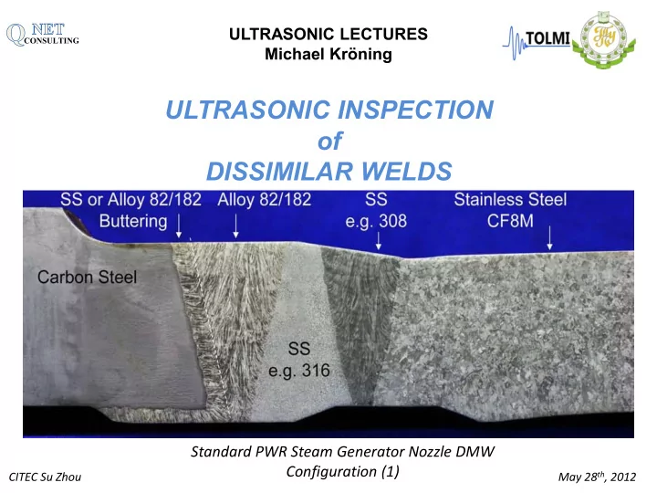
Standard PWR Steam Generator Nozzle DMW Configuration (1)
ULTRASONIC INSPECTION of DISSIMILAR WELDS Standard PWR Steam - - PowerPoint PPT Presentation
ULTRASONIC LECTURES CONSULTING Michael Krning ULTRASONIC INSPECTION of DISSIMILAR WELDS Standard PWR Steam Generator Nozzle DMW Configuration (1) May 28 th , 2012 CITEC Su Zhou CONSULTING State-of-the-Art Ultrasonic Material Inspection
CONSULTING
CITEC Su Zhou May 28th, 2012
ULTRASONIC LECTURES Michael Kröning
Standard PWR Steam Generator Nozzle DMW Configuration (1)
CONSULTING
CITEC Su Zhou May 28th, 2012 Austenitic Weld Dissimilar Weld
State-of-the-Art Ultrasonic Material Inspection
Limitations
A Scan
CONSULTING
CITEC Su Zhou May 28th, 2012
Fracture Surface of Alloy 182 Weld Metal with Irregular Crack Front (2)
CONSULTING
CITEC Su Zhou May 28th, 2012
Cracking Susceptibility of various Alloys (3)
CONSULTING
CITEC Su Zhou May 28th, 2012
Component Item Date PWSCC Initially Observed Service Lifea (Calendar Years) Steam Generator Hot Leg Tubes and Plugs ~1973 ~2 Pressurizer Instrument Nozzles 1986 2 Steam Generator Cold Leg Tubes 1986 18 Pressurizer Heaters and Sleeves 1987 5 Steam Generator Channel Head Drain Pipes 1988 1 Control Rod Drive Mechanism Nozzles 1991 12 Hot Leg Instrument Nozzles 1991 5 Power Operated Relief Valve Safe End 1993 22 Pressurizer Nozzle Welds 1994 1 Cold Leg Piping Instrument Nozzles 1997 13 Reactor Vessel Hot Leg Nozzle Buttering/Piping Welds 2000 17 Control Rod Drive Mechanism Nozzle/RV Head Welds 2000 27 Surge Line Nozzle Welds 2002 21 Reactor Vessel Lower Head In-Core Instrumentation Nozzles/Welds 2003 14
Alloy 600 PWSCC Experience in Commercial PWRs Crack Initiation Times
CONSULTING
CITEC Su Zhou May 28th, 2012
WATER CHEMISTRY STRESS STATE MATERIAL STATE
CONSULTING
CITEC Su Zhou May 28th, 2012
2000 F.N. Speller Award Lecture by P.M. Scott, Framatome.
CONSULTING
CITEC Su Zhou May 28th, 2012
WATER CHEMISTRY
(thermally-activated mechanism )
CONSULTING
CITEC Su Zhou May 28th, 2012
Effect of zinc on corrosion rates of various alloys in laboratory tests (after Esposito et al.)
CONSULTING
CITEC Su Zhou May 28th, 2012
Example for the effect of zinc on time to initiate PWSCC in laboratory tests (after Esposito et al. 1991)
CONSULTING
CITEC Su Zhou May 28th, 2012
Degradation Factor as a Function of Temperature (ref. (David R. Forsyth, 2005))
CONSULTING
CITEC Su Zhou May 28th, 2012
STRESS STATE
CONSULTING
CITEC Su Zhou May 28th, 2012
Effects of heat treatment on SCC susceptibility
stress relief annealing
CONSULTING
CITEC Su Zhou May 28th, 2012
CONSULTING
CITEC Su Zhou May 28th, 2012
MATERIAL STATE
(threshold for PWSCC resistance: between 22 and 30% chromium)
(no repair, weld bead size, heat treatment, weld design)
lack of fusion areas, promote PWSCC by acting as stress concentrators )
CONSULTING
CITEC Su Zhou May 28th, 2012
Assessment of Dissimilar Welds: “Risk for PWSCC”
CONSULTING
CITEC Su Zhou May 28th, 2012
CONSULTING
CITEC Su Zhou May 28th, 2012
NDT SUPPORTED MITIGATION CONCEPT
CONSULTING
CITEC Su Zhou May 28th, 2012
CONSULTING
CITEC Su Zhou May 28th, 2012
a b c
a - standard pipe to pipe weld b - narrow gap weld c - dissimilar weld
PHOTOMICROGRAPHS
WELD SECTIONS
CONSULTING
CITEC Su Zhou May 28th, 2012
A-Scan Image
Impulse – Echo Technique
45° Shear Wave Transducer
CONSULTING
CITEC Su Zhou May 28th, 2012
A-Scan Image
Impulse – Echo Technique
45° Shear Wave Transducer
A-Scan Image
CONSULTING
CITEC Su Zhou May 28th, 2012
CONSULTING
CITEC Su Zhou May 28th, 2012
30 60 90 120 150 180 210 240 270 300 330 6000 4000 2000
Q
CONSULTING
CITEC Su Zhou May 28th, 2012
Model of the transverse isotropic structure of stainless steel weld joints Vph = Phase Velocity; Cij = Elastic Constant; ρ - Density, Φ – Fiber Orientation
CONSULTING
CITEC Su Zhou May 28th, 2012
CONSULTING
CITEC Su Zhou May 28th, 2012
False Call by Interface Reflection
Quantitative Ultraschallprüfungen an anisotropen Materialien mittels Sampling Phased Array Technik,
DGZfP-Jahrestagung 2010
CONSULTING
CITEC Su Zhou May 28th, 2012
CONSULTING
CITEC Su Zhou May 28th, 2012
CARBON FIBER MODEL COMPOSITE
CONSULTING
CITEC Su Zhou May 28th, 2012
*Simulation by:
Fraunhofer IZFP
Modeling of sound propagation in transverse isotropic media*
0 dB
25 25
CARBON FIBER MODEL COMPOSITE Φ = -45°
CONSULTING
CITEC Su Zhou May 28th, 2012
FOKUSSING & DEFOKUSSING OF SOUND FIELDS IN TRANSVERSE ISOTRPIC MATERIALS
CONSULTING
CITEC Su Zhou May 28th, 2012
R&D Reverse Phase Matching
Inspection of carbon-fiber structures
Angle beam (12°) insonification
Sampling Phased array Conventional phased array
CONSULTING
CITEC Su Zhou May 28th, 2012
Transverse and Longitudinal Sections with Homogeneous Anisotropic Structure
CONSULTING
CITEC Su Zhou May 28th, 2012
Vertical weld, pipe horizontal Horizontal weld pipe vertical
CONSULTING
CITEC Su Zhou May 28th, 2012
TRANSVERSAL ISOTROPIC DOMAINS TID
STRIP MODEL PIXEL/VOXEL MODEL
CONSULTING
CITEC Su Zhou May 28th, 2012
a Test Specimen b Phased Array c Sampling Phased Array d Sampling Phased Array Phases Matched REFLECTOR POSITIONING BY MODEL SUPPORTED PHASE MATCHING
CONSULTING
CITEC Su Zhou May 28th, 2012
CONSULTING
CITEC Su Zhou May 28th, 2012
CONSULTING
CITEC Su Zhou May 28th, 2012
Case Studies: Surfaces
Simulation by Dr. Schubert
Fraunhofer IZFP-D
Transducer: normal probe f = 4 MHz Aperture: A = 10 mm Surface: flat
Snap Shot maximum intensity
CONSULTING
CITEC Su Zhou May 28th, 2012
Water gap depth (lense shaped): 0.74 mm (/2 in steel, 2 in water)
CONSULTING
CITEC Su Zhou May 28th, 2012
Water gap depth (lense shaped):
0.18 mm (/8 in steel, /2 in water)
CONSULTING
CITEC Su Zhou May 28th, 2012
CONTOUR ANALYSIS
Surface Contour of Pipe to Elbow Weld
CONSULTING
CITEC Su Zhou May 28th, 2012
LOCALIZATION OF REFLECTOR INDICATIONS
CONSULTING
CITEC Su Zhou May 28th, 2012
REGISTRATION: AMPLITUDE CRITERIA IN REFERENCE TO CALIBRATION REFLECTORS EVALUATION: LOCALIZATION, CONTRAST & RESOLUTION SENSITIVITY
CONSULTING
CITEC Su Zhou May 28th, 2012
CONSULTING
CITEC Su Zhou May 28th, 2012
INSPECTION BY CAUSE DEFECT MODELING MICROSTRUCTURE SCATTERING REDUCTION ASSESSMENT OF TI DOMAINS SOUND PROPAGATION
CONSULTING
CITEC Su Zhou May 28th, 2012
»Inspection by Highly Qualified Scientists«
= 45°
L Tv
= 60°
GW SN
Example of inspection planning
(1) Simulation of US wave propagation
List of Possible Transducers
(3) Qualification of inspection technique & testing personnel
(2) Choice of appropriate transducers
CONSULTING
CITEC Su Zhou May 28th, 2012
= 45°
L Tv
= 60°
75° L 60° L 45° T
Phased Array
45- 80° L 35- 80° T
REPLACEMENT OF TRANSDUCERS
CONSULTING
CITEC Su Zhou May 28th, 2012
The ZETEC Advanced Phased Array Calculator is Useful for Generating Focal Laws (left) and Simulating the Sound Field for the Focal Law (right) to Determine Beam Characteristics
CONSULTING
CITEC Su Zhou May 28th, 2012
CONSULTING
CITEC Su Zhou May 28th, 2012
The Principle of Inverse Phase Matching Calculation of time of flight in consideration of acoustic anisotropy Phase corrected summation
ij ij t
RESEARCH & DEVELOPMENT REVERSE PHASE MATCHING
CONSULTING
CITEC Su Zhou May 28th, 2012
Phased array transducer and test specimen Conventional Phased Array
Backwall
Sampling Array with Reverse Phase Matching
Backwall Notch tip
Ultrasonics
C
CONSULTING
CITEC Su Zhou May 28th, 2012
B- Scan D- Scan C- Scan
8 mm 42 mm
US- Probe:
Technique:
with SAFT Reconstruction
Inspection of austenitic narrow gap weld with root crack
CONSULTING
CITEC Su Zhou May 28th, 2012 8 mm 42 mm
Inspection of austenitic narrow gap weld with root crack 3D VISUALIZATION
CONSULTING
CITEC Su Zhou May 28th, 2012