
SLIDE 1
1/13
Transmission Impairments
Surasak Sanguanpong nguan@ku.ac.th http://www.cpe.ku.ac.th/~nguan
Last updated: 25 November 2004
2/13
Transmission Impairments Surasak Sanguanpong nguan@ku.ac.th - - PDF document
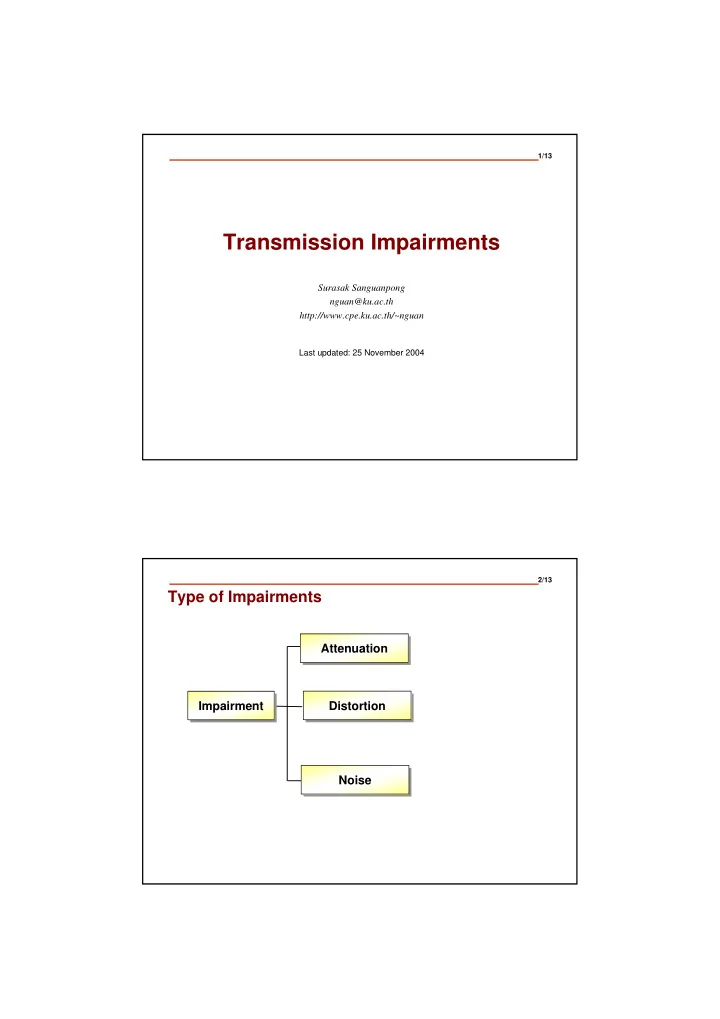
1/13 Transmission Impairments Surasak Sanguanpong nguan@ku.ac.th http://www.cpe.ku.ac.th/~nguan Last updated: 25 November 2004 2/13 Type of Impairments Attenuation Attenuation Impairment Distortion Impairment Distortion Noise Noise
1/13
Surasak Sanguanpong nguan@ku.ac.th http://www.cpe.ku.ac.th/~nguan
Last updated: 25 November 2004
2/13
3/13
Transmitter Receiver Amplifier
P1 P2 P4 P3
4/13
1
2 3
Amplifier
Power ratio Decibel Value 1 0 2 3 4 6 8 9 10 10 100 20 1000 30 Power ratio Decibel Value 1 0 2 3 4 6 8 9 10 10 100 20 1000 30
5/13
Components are in phase Transmitter Receiver Components are out of phase
6/13
7/13
Atmospheric Noise
Lightning : static discharge of clouds Solar noise : sun’s ionized gases Cosmic noise : distant stars radiate high frequency signal
Gaussian Noise
Thermal noise : generated by random motion of free electrons
Crosstalk
NEXT FEXT
Impulse Noise : sudden bursts of irregularly pulses
8/13
distorted a transmitted signal attenuated a transmitted signal
9/13
The BER (Bit Error Rate) is the probability of a
BER of 10-5 means on average 1 bit in 10-5 will be
A BER of 10-5 over voice-graded line is typical. BERs of less than 10-6 over digital communication is
10/13
NEXT (near-end crosstalk)
interference in a wire at the transmitting end of a signal
FEXT (far-end crosstalk)
interference in a wire at the receiving end of a signal
11/13
12/13
13/13
Transmitter Receiver
0101110101010111110 010110101111111
Throughput = Number of bits passing through in a second
Transmitter Receiver
0101110 0101110
distance=D t1 t2 propagation delay = t2-t1 = D/propagation speed