Time triggered real time communication Presentation overview - - PDF document

time triggered real time communication
SMART_READER_LITE
LIVE PREVIEW

Time triggered real time communication Presentation overview - - PDF document

Roger Johansson/ 2011 Time triggered real time communication Presentation overview Background automotive electronics, an application area for time triggered communication. Time triggered protocols TTPC, first commercial implementation.


slide-1
SLIDE 1

Roger Johansson/ 2011 Time triggered real time communication 1

 Background

automotive electronics, an application area for time triggered communication.

 Time triggered protocols

TTPC, first commercial implementation. Originally from TU Vienna. Operational in civil aircrafts. TTCAN, based on Controller Area Network (CAN) which is widely used in today's vehicular electronic systems. FlexRay, based on BMW’s “ByteFlight”. Anticipated in next generation automotive electronic systems.

 Hybrid scheduling

combining static scheduling with fixed priority scheduling analysis.

Time triggered real time communication

Presentation overview

Roger Johansson/ 2011 Time triggered real time communication 2

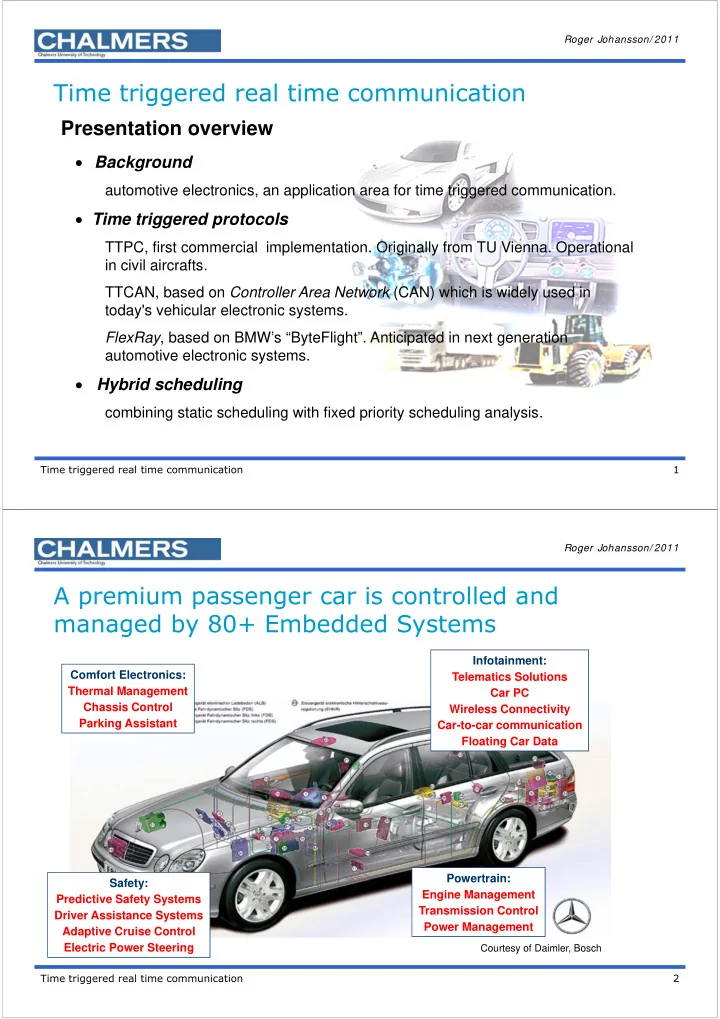
A premium passenger car is controlled and managed by 80+ Embedded Systems

Powertrain: Engine Management Transmission Control Power Management Comfort Electronics: Thermal Management Chassis Control Parking Assistant Safety: Predictive Safety Systems Driver Assistance Systems Adaptive Cruise Control Electric Power Steering Infotainment: Telematics Solutions Car PC Wireless Connectivity Car-to-car communication Floating Car Data

Courtesy of Daimler, Bosch

slide-2
SLIDE 2

Roger Johansson/ 2011 Time triggered real time communication 3

  • All variants of a specific

model are physically identical and differ only in their individual software configuration

  • The various included

physical components can be activated or deactivated by the software

Motor configuration B Motor configuration A

Variant 2 Variant 1

Entertainment configuration A Entertainment configuration F

Virtual differentiation between variants

Roger Johansson/ 2011

1927 1927 1975 1975 1982 1982 1944 1944 1997 1997 1966 1966 1956 1956

4 4 5 5 7 7 9 9 16 16 54 54 27 27

1200 1200 575 575 283 283 183 183 83 83 50 50 30 30

  • No. of fuses
  • No. of
  • No. of

meters of meters of electric electric wires wires

Electrical system 1927-1997

Wiring diagram, Volvo ÖV4 (“Jacob”) 1927

Time triggered real time communication 4

slide-3
SLIDE 3

Roger Johansson/ 2011

The evolution of the electrical system

1970 1980 1990 2000 2010

Architecture Optimisation on many levels Standardised interfaces Power production and distribution Simple components More complex functions stand-alone systems ABS, Airbag Integration of systems Optimisation of information Common data busses

Time triggered real time communication 5

50 100 150 200 250 300 350 400 450 1930 1940 1950 1960 1970 1980 1990 1995 2000 2005

# of functions # of integrated functions

Features

Roger Johansson/ 2011 Time triggered real time communication 6

Automotive electronics roadmap

slide-4
SLIDE 4

Roger Johansson/ 2011

An electrical system…

CAN CAN Power Train Light Sub-Bus ITS Window Lift Interior Light Lock Mirror Lock Mirror Lock Lock Seat Htng Seat Htng Instruments Central Body Ctrl Climate Universal Motor Universal Panel Light Roof St-Wheel Panel x6 Htng Htng Seat Wiper Trunk WHtg Universal Light Time triggered real time communication 7 Roger Johansson/ 2011

Control units Module

Conventional system Network

Identifier Data Command Control

Engine Control Automatic Transmission Central Module Driver Information

Multiplex Networks

Time triggered real time communication 8

slide-5
SLIDE 5

Roger Johansson/ 2011 Time triggered real time communication 9

By-wire control

The F-8 Digital Fly-By-Wire (DFBW) flight research project validated the principal concepts of all-electric flight control systems now used on nearly all modern high-performance aircraft and on military and civilian transports. The first flight of the 13-year project was on May 25, 1972.

Courtesy of Dryden Flight Research Center Hydraulic information carrier Electronic information carrier Roger Johansson/ 2011 Time triggered real time communication 10 traffic control local control train (consist) control

((( ))) ((( )))

wayside control traffic control local control train (consist) control

((( ))) ((( )))

wayside control

Electronics in distributed control

slide-6
SLIDE 6

Roger Johansson/ 2011 Time triggered real time communication 11

Drive-by-wire

Roger Johansson/ 2011 Time triggered real time communication 12

Local control

  • Local information processing
  • Independent control objects

Centralized global control

  • Local and central information processing
  • Interconnected control objects

Distributed global control

  • Local and distributed information processing
  • Interconnected control objects

Control system implementation strategies

slide-7
SLIDE 7

Roger Johansson/ 2011 Time triggered real time communication 13

Non-functional requirements

System life time

System Architecture

Produceability Availability Security Understandability Usability Safety Conceptual integrity Timeliness Changeability Interoperability Reliability Performance/ Efficiency Testability Cost-effectiveness Maintainability Extendability Portability Restructuring Robustness Fault tolerance Variability (variants, configurations)

Roger Johansson/ 2011 Time triggered real time communication 14

Tradeoffs from Safety/Reliability requirements

 In a distributed environment, only time triggered protocols and redundant buses can provide this safety. Contemporary TTP’s are:

TTP/C, first commercial implementation. Originally from TU Vienna. Operational in civil aircrafts. TTCAN, based on Controller Area Network (CAN) which is widely used in today's vehicular electronic systems. FlexRay, based on BMW’s “ByteFlight”. Operational in contemporary automotive electronic systems. The extremes from reliability requirements leads to safety requirements. Safety requirements implies redundancy, (Fail-Operational, Fail-Safe, etc). Safety requirements also demands predictability, we has to show, a priori, that the system will fulfill it’s mission in every surrounding at every time.

slide-8
SLIDE 8

Roger Johansson/ 2011 Time triggered real time communication 15

– Based on the CAN protocol – Bus topology – Media: twisted pair – 1Mbit/s

TTCAN

Node 1 Node 4 Node 3 Node 2 Node 6 Node 5 Node 7

A second controller is required to implement the redundant bus

A S S S

CPU/mem /CC

Nod

Roger Johansson/ 2011 Time triggered real time communication 16

TTCAN

”Exclusive” – guaranteed service ”Arbitration” – guaranteed service (high ID), best effort (low ID) ”Reserved” – for future expansion...

Basic cycle 0 Basic cycle 1 Basic cycle 2 Basic cycle 3

Transmission Columns

t Time is global and measured in network time units (NTU’s)

slide-9
SLIDE 9

Roger Johansson/ 2011 Time triggered real time communication 17

TTP/C

CNI works as a “firewall” Status, global time, membership Control, clock interrupt Watchdog, checking consensus Data the actual message

– Double channels (one redundant). Bus topology or ”star” (optical) – Media: twisted pair, fibre – 10 Mbit/s for each channel

A network is built on either twin buses or twin stars.

A S S S

CPU/mem /CC

Nod

CNI

Nod Nod 1 Nod Nod 4 Nod Nod 3 Nod Nod 2 Nod Nod 6 Nod Nod 5

A B

Nod Nod 1 Nod Nod 2 Nod Nod 3 Nod Nod 4 Nod Nod 5 Nod Nod 6 Roger Johansson/ 2011 Time triggered real time communication 18

TTP/C

All communication is statically scheduled

Guaranteed service

Non periodical messages has to been fitted into static slots by the application

”TDMA-round”

”message slots” t

slide-10
SLIDE 10

Roger Johansson/ 2011 Time triggered real time communication 19

Flexray

– Double channels, bus or star (even mixed). – Media: twisted pair, fibre

– 10 Mbit/s for each channel

Nod 1 Nod 4 Nod 3 Nod 2 Nod 6 Nod 5

A B

Nod 7

A S S S

CPU/mem/ CC

Nod

Redundant channel can be used for an alternative schedule

Roger Johansson/ 2011 Time triggered real time communication 20

”Static segment” (compare TTCAN ”Exclusive”) – guaranteed service ”Dynamic segment” (compare TTCAN ”Arbitration”) – guaranteed service (high ID), ”best effort” (low ID)

Guaranteed periodical Guaranteed periodical/ aperiodical ”Best-effort” aperiodical 63 62 3 2 1 Network Idle Time Symbol window Static segment (m slots) Dynamic segment (n mini-slots)

Flexray

Max 64 nodes on a Flexray network.

slide-11
SLIDE 11

Roger Johansson/ 2011 Time triggered real time communication 21

Comparisons

All protocols are suitable for scheduling tools.

TTP/C has commercial production tools. Tools for TTCAN and Flexray are anticipated.

All protocols targets real time applications.

TTCAN and Flexay combines time AND event triggered paradigms well.

CAN, many years experiences, a lot of existing applications.

Implies migration of existing CAN applications into TTCAN.

Flexray is the latest initiative.

Supported by most automotive suppliers.

TTP/C considered as complex.

Poor support for asynchronous events. High complexity, lacks second (or multiple) sources.

Roger Johansson/ 2011 Time triggered real time communication 22

Combining time triggering with events: Exam ple of Hybrid scheduling for TTCAN

Messages are sorted into three different categories:

 Hard real-time, for minimal jitter with guaranteed response time.  Firm real-time, for guaranteed response time, but can tolerate jitter.  Soft real-time, for “best effort” messages.

slide-12
SLIDE 12

Roger Johansson/ 2011 Time triggered real time communication 23

TTCAN detailed study

Q T i i i i

Q T B R   

B Response time analysis

Roger Johansson/ 2011 Time triggered real time communication 24

Time triggered messages Mh

After structuring: M : {Mh, Mf, Ms}, assume that at least Mh is defined. We now construct a matrix

  • cycle. Due to protocol constraints, the schedule has to fulfil:

LCM( Mh

p ) = x 2n

where:  LCM is least common multiple period for the Mh message set;  x is the preferred length of a basic cycle within LCM;  n is the number of basic cycles. Hardware constraints: Hwc1: 1 ≤ x ≤ 2y, has to be consistent with a hardware register, y bits Hwc2: 0 ≤ n ≤ k, always a power of 2, constraint in hardware. Hwc3: # of triggers ≤ Tr, columns in the matrix cycle. Limited by the number of available trigger registers.

Basic cycle 0 Basic cycle 1 Basic cycle 2 Basic cycle 3 Transmission Columns time windows

slide-13
SLIDE 13

Roger Johansson/ 2011 Time triggered real time communication 25

Multiple solutions satisfies the equation...

Choose a strategy: Strategy 1 :

Minimize number of basic cycles, requires a longer basic cycle, and more triggers.

Strategy 2 :

Minimize length of basic cycles, increase probability of finding a feasible schedule for large message

Roger Johansson/ 2011 Time triggered real time communication 26

Persuing the strategies...

Construct a schedule for the following set: M h = ( M1, M2 , M3) with the following attributes (NTU): M1p = 1000, M1e = 168 M2p = 2000, M2e = 184 M3p = 3000, M3e = 216 It’s obvious that: LCM( M1, M2 , M3 ) = 6000. and: 6000 = x 2n

slide-14
SLIDE 14

Roger Johansson/ 2011 Time triggered real time communication 27

Minimizing number of basic cycles yields: 2n = 1, so n = 0 and x = 6000. Hwc1 and Hwc2 are fulfilled. Total numbers of triggers for N messages in one basic cycle is: in this case: # of triggers = So, strategy 1, leads to a solution with:  1 basic cycle and 11 triggers.  MAtrix cycle length is 6000 NTU.

Strategy 1

Basic Cycle Triggers

168 352 1000 2000 2168 3000 3352 4000 4168 5000 M1 M2 M3 M1 M1 M2 M1 M3 M1 M2 M1

 N i i

M ) LCM(

1

M

11 3000 6000 2000 6000 1000 6000   

Roger Johansson/ 2011 Time triggered real time communication 28

n = 0: 6000 = x 20  x = 6000 (same as strategy 1) n = 1: 6000 = x 21  x = 3000 n = 2: 6000 = x 22  x = 1500 n = 3: 6000 = x 23  x = 750 n = 4 : 6 0 0 0 = x 2 4  x = 3 7 5 n = 5: 6000 = x 25  x = 187.5

Basic cycle 1 (at 0) 2 (at 375) 3 (at 750) 4 (at 1125) 5 (at 1500) 6 (at 1875) 7 (at 2250) 8 (at 2625) 9 (at 3000) 10 (at 3375) 11 (at 3750) 12 (at 4125) 13 (at 4500) 14 (at 4875) 15 (at 5250) 16 (at 5625)

  • 3000
  • 4125
  • 168
  • 4168
  • 352
  • 2000
  • 2168
  • 1000
  • 3352
  • 4000
  • 5000
  • Trigger

Information Minimum Triggers

1 M1 M2 M3 3 2 3 M1 1 4 5 6 M1 M2 2 7 8 9 M1 M3 2 10 11 M1 ? 1 12 ? M1 M2 2 13 14 M1 1 15 16

Strategy 2

slide-15
SLIDE 15

Roger Johansson/ 2011 Time triggered real time communication 29

Avoid this conflict with the requirement that: a basic cycle shall be at least as long as the shortest period in the message set. Applying this restriction we get: n = 2, (x = 1500) which yields a feasible schedule:

Basic cycle 1 2 3 4

  • 3000
  • 168
  • 352
  • 3352
  • 2000
  • 5000
  • 2168
  • 4000
  • 1000
  • 4168
  • Trigger

Information Minimum Triggers

1 M1 M2 M3 M1 4 2 M1 M2 2 3 M1 M3 M1 M2 4 4 M1 1

Strategy 2

Roger Johansson/ 2011 Time triggered real time communication 30

Verifying the events... (Mf)

Grey slots are supposed to be allocated for M h Basic Cycle NTU-slots (Columns) 1 q0 2 q1 q2 3 q3 q4 q5 ….. … … … … 2n qN-3 qN-2 qN-1

for each message m in M f : for message m = 1 up to last_m for virtual message VMi = 1 up to last_VM if( Qm + Tm ) falls within ( VMi,start , VMi,completion ) Qm = VMi,completion else endif end end end

j P P j j m m

T t Q Q

j m

 

        

1 :

slide-16
SLIDE 16

Roger Johansson/ 2011 Time triggered real time communication 31

Conclusions

 Applicable real time communication protocols for future

safety-critical applications has to provide strictly periodical (minimal jitter), periodical (jitter is negliable) and a-periodic communication to fully support control applications. Scheduling periodical and a-periodical events requires a new approach, hybrid scheduling.  Hybrid scheduling is sparsely found in today’s literature...

Roger Johansson/ 2011 Time triggered real time communication 32

Time triggered real time communication

Thank you for your attention.