real real time systems time systems
play

Real- Real -Time Systems Time Systems Real- -Time Systems Time - PowerPoint PPT Presentation

EDA222/DIT160 Real-Time Systems, Chalmers/GU, 2008/2009 Lecture #15 Updated 2009-03-03 Dependable Distributed Dependable Distributed Real- Real -Time Systems Time Systems Real- -Time Systems Time Systems Real Aircraft/automotive


  1. EDA222/DIT160 – Real-Time Systems, Chalmers/GU, 2008/2009 Lecture #15 Updated 2009-03-03 Dependable Distributed Dependable Distributed Real- Real -Time Systems Time Systems Real- -Time Systems Time Systems Real 
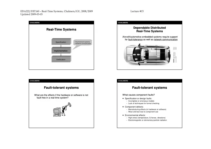
Aircraft/automotive embedded systems require support Aircraft/automotive embedded systems require support for for fault fault- -tolerance tolerance as well as as well as network communication network communication • Fault-tolerant systems Specification • Network communication Implementation Verification Fault- -tolerant systems tolerant systems Fault- -tolerant systems tolerant systems Fault Fault What are the effects if the hardware or software is not What causes component faults? What causes component faults? What are the effects if the hardware or software is not • Specification or design faults: fault- -free in a real free in a real- -time system? time system? fault – Incomplete or erroneous models – Lack of techniques for formal checking • Component defects: – Manufacturing effects (in hardware or software) – Wear and tear due to component use • Environmental effects: – High stress (temperature, G-forces, vibrations) – Electromagnetic or elementary-particle radiation

  2. EDA222/DIT160 – Real-Time Systems, Chalmers/GU, 2008/2009 Lecture #15 Updated 2009-03-03 Fault- Fault -tolerant systems tolerant systems Fault- Fault -tolerant systems tolerant systems What types of faults are there? What types of faults are there? How are faults handled at run- How are faults handled at run -time? time? • Permanent faults: • Error detection: – Total failure of a component – Erroneous data or program behavior is detected • Watchdog mechanism, comparisons, diagnostic tests – Caused by, e.g., short-circuits or corrupted data structures • Error correction: – Remains until component is repaired or replaced • Transient faults: – The originally-intended data/behavior is restored • Intelligent codes used for restoring corrupt data – Temporary malfunctions of a component • Check-pointing used for restoring corrupt program flow – Caused by, e.g., ion radiation or power fluctuation • Fault masking: • Intermittent faults: – Effects of erroneous data or program behavior are ”hidden” • Time (re-execute code) or space (replicated hardware) redundancy – Repeated occurrences of transient faults • Voting mechanism (e.g., majority voting) or N-modular redundancy (i.e., 2 m +1 units to mask m faults) Fault- -tolerant systems tolerant systems Network communication Fault Network communication To extend real- To extend real -time computing towards fault time computing towards fault- -tolerance, tolerance, the following issues must be considered: the following issues must be considered: Hardware platform μ μ 1. What is the fault model used? 1 4 τ τ – What type of fault is assumed? sender receiver 1 2 – How and when are faults detected? message 2. How should fault-tolerance be implemented? – Using time redundancy (re-execution)? – Using space redundancy (replicated tasks/CPUs/networks)? μ μ 2 3 3. What scheduling policy should be used? – Extend existing policies? – Suggest new policies?

  3. EDA222/DIT160 – Real-Time Systems, Chalmers/GU, 2008/2009 Lecture #15 Updated 2009-03-03 Network communication Network communication Network communication Network communication Message delay: Message delay: τ τ • Message delays are caused by the following overheads: T 1 T 2 1 2 – Formatting (packetizing) the message – Queuing the message, while waiting for access to medium message delay – Transmitting the message on the medium τ 1 – Notifying the receiver of message arrival t – Deformatting (depacketizing) the message network t Formatting/deformatting Formatting/ deformatting overheads are typically included in overheads are typically included in τ the execution time of the sending/receiving task. the execution time of the sending/receiving task. 2 t Network communication Network communication Network communication Network communication Queuing delay: Transmission delay: Queuing delay: Transmission delay: • The cause of the queuing delay for a message depends • The delay for transmitting the message is a function of: on the actual network used. For example: – Message length (bits) N = – Waiting for a corresponding time slot (TDMA) frame t frame – Data rate (bits/s) R – Waiting for a transmission token (Token Ring) and – Waiting for a contention-free transmission (Ethernet) – Waiting for network priority negotiation (CAN) – Communication distance (m) L = t prop – Signal propagation velocity (m/s) v

  4. EDA222/DIT160 – Real-Time Systems, Chalmers/GU, 2008/2009 Lecture #15 Updated 2009-03-03 Network communication Network communication Network communication Network communication How is the message transferred onto the medium? How is the message transferred onto the medium? TDMA- TDMA -based protocols: based protocols: • Contention-free communication: • One or more dedicated time slots for each processor: – Example: medium access is divided into minor communication – Senders need not contend for medium access at run-time cycles (CC) and major system cycles (SC) – Time-division, multiple-access (TDMA) – Message queuing delay is bounded (can be made negligible • Token-based communication: with appropriate scheduling) • Examples: – Each sender using the medium gets one chance to send its messages, based on a predetermined order – TTP/C (Time-Triggered Protocol) • Collision-based communication: – FlexRay – Senders may have to contend for the medium at run-time – Ethernet, CAN Network communication Network communication Network communication Network communication Token- -based protocols: based protocols: Ethernet- -based protocols: based protocols: Token Ethernet • Utilize a token for the arbitration of message transmissions • Senders attempt to send a complete message on a shared medium – Collision-detect mechanism is used to determine if there is a need for re-transmission – The sender is only allowed to transmit its messages when it – Message queuing delay can in general not be bounded! possesses the token – Message queuing delay is bounded CAN protocol: CAN protocol: • Examples: • Senders transmit a message header (with an identifier) – Token Bus (IEEE 802.4) – Collision-detect mechanism is used to determine who – Token Ring (IEEE 802.5) will be allowed to send the entire message – FDDI – Message queuing delay can be bounded with appropriate identifier assignment

  5. EDA222/DIT160 – Real-Time Systems, Chalmers/GU, 2008/2009 Lecture #15 Updated 2009-03-03 The CAN protocol The CAN protocol The CAN protocol The CAN protocol Controller Area Network (CAN): (Bosch 1991, SAE 1993) Controller Area Network (CAN): (Bosch 1991, SAE 1993) CAN message frame format: (short format) CAN message frame format: (short format) SOF 11-bit identifier control 0 - 8 bytes of message data error control Ack EOF μ μ 1 4 11-bit identifier is used for two purposes: • assign a priority to the message (low number ⇒ high priority) collision-detect broadcast bus • enable receiver to filter messages Wired- -AND AND: Wired μ μ Each node monitors the bus while transmitting. 2 3 If multiple nodes are transmitting simultaneously and one node transmits a ’0’, then all nodes will see a ’0’. If all nodes transmit a ’1’, then all nodes will see a ’1’. The CAN protocol Dependable distributed networks The CAN protocol Dependable distributed networks CAN protocol: (binary countdown) Contemporary communication networks suitable for Contemporary communication networks suitable for CAN protocol: (binary countdown) dependable distributed real- -time systems time systems dependable distributed real 1. Each node with a pending message waits until bus is idle. • TTCAN: 2. The node begins transmitting the highest-priority message pending on the node. Identifier is transmitted first, in the order – Widely used in today's automotive electronic systems of most-significant bit to least-significant bit. • TTP/C: 3. If a node transmits a recessive bit (’1’) but sees a dominant bit (’0’) on the bus, then it stops transmitting since it is not – Operational in civil aircrafts transmitting the highest-priority message in the system. • FlexRay: 4. The node that transmits the last bit of its identifier without detecting a bus inconsistency has the highest priority and can – Anticipated in next generation automotive electronic systems start transmitting the body of the message.

Download Presentation
Download Policy: The content available on the website is offered to you 'AS IS' for your personal information and use only. It cannot be commercialized, licensed, or distributed on other websites without prior consent from the author. To download a presentation, simply click this link. If you encounter any difficulties during the download process, it's possible that the publisher has removed the file from their server.

Recommend


More recommend