
SLIDE 1
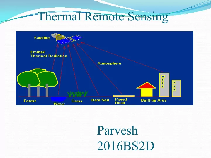
Thermal Remote Sensing Parvesh 2016BS2D Thermal infrared of EM - - PowerPoint PPT Presentation
Thermal Remote Sensing Parvesh 2016BS2D Thermal infrared of EM spectrum All objects have a temperature above absolute zero (0 K) emit EM energy (in 3.0-100 m). Human being has normal 98.6 F (37 C) 100 m 100 m Our eyes
All objects have a temperature
above absolute zero (0 K) emit EM energy (in 3.0-100 µm).
Human being has normal
98.6 ºF (37 ºC)
Our eyes are only sensitive to
visible energy (0.4-0.7 µm).
100 m
Our eyes are only sensitive to
visible energy (0.4-0.7 µm). Human sense thermal energy through touch. while detectors (sensors) are sensitive to all EM spectrum.
All objects (vegetation, soil,
rock, water, concrete, etc) selectively absorb solar short- wavelength energy and radiate thermal infrared energy.
0.7 m 3.0 m 100 m
Optical remote sensing (visible and near-IR)
Examine abilities of objects to reflect solar radiation
Emissive remote sensing (mid-IR and microwave)
Examine abilities of objects to absorb shortwave visible Examine abilities of objects to absorb shortwave visible
and near-IR radiation and then to emit this energy at longer wavelengths
Thermal IR Infrared (IR) waves:
Within a given window, the atmospheric intervention
Atmospheric absorption and scattering make signals Atmospheric absorption and scattering make signals
Both effects are directly related to atmospheric path
The windows normally used for aircraft platforms are in the 3-5 micron and 8-14 micron wavelength regions Spaceborne sensors commonly use windows between 3 and 4 micron and between 10.5-12.5 micron None of the windows transmits 100 % because water vapor and carbon dioxide absorb some of the energy across the spectrum and ozone absorbs energy in the 10.5-12.5 micron
Sun
Reflected path radiance Emitted
Satellite electromagnetic sensors “see” reflected and emitted radiation
Incident Absorbed Transmitted Reflected target radiance Emitted path radiance Emitted target radiance
The amount of radiation emitted by an object is
internal temperature and emissivity
Plank's Radiation Law for blackbodies gives the position of the peak and total Plank's Radiation Law for blackbodies gives the position of the peak and total spectral radiance (area under the curve) of an object as a function of its temperature E= Energy or total radiant exitance, W m-2 h = Placnk’s constant k = Boltzmann constant c = speed of light (constant) T = temperature (in K) λ = Wavelength
Notice that the peak of the Blackbody curve shirts to shorter wavelengths as temperature increases temperature increases This peak represents the wavelength
Developments from Planck’s Law Stefan-Boltzmann Law
The Stefan-Boltzmann law is derived by integrating the Planck function with respect to wavelength:
E = σT4
σ is called the Stefan-
Stefan-Boltzmann Law: the amount of energy emitted from an object is primarily a function of its temperature.
σ is called the Stefan- Boltzmann constant. σ = 5.667 x 10⁻⁸
Energy or the radiant flux (rate of flow of EM energy)
Conclusion: Thermal IR: 3 to 14 μm Thermal Remote Sensing explained by three law’s Plank’s Radiations law Wein Displacement law derived from Plank’s law Stefan-Boltzmann Law