SLIDE 1
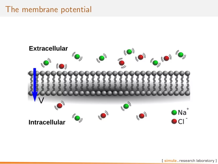
The membrane potential
SLIDE 2
Flow through a semi-permeable membrane
Consider two solutions: A: Contains 100mM Cl− ions and 100mM Na+ ions B: Contains 10mM Cl− ions and 10mM Na+ ions Both are neutral.
SLIDE 3
Flow through a semi-permeable membrane
If they are only separated by a membrane permeable to Cl− but not Na+, this will happen: Cl− will diffuse from A to B due the concentration gradient [Cl−]A will drop and [Cl−]B will increase [Na+]A and [Na+]B will remain fixed (no flow) A and B will no longer be neutral An electrical force will attract Cl− towards A
SLIDE 4
Flow through a semi-permeable membrane
The cell membrane is semi-permeable. The semi-permeability is provided by for example ion channels V is called the membrane potential and is defined by Vi − Ve
SLIDE 5
The Nernst Equilibrium Potential
We now have two forces driving Cl− across the membrane: Flow from A to B due to the concentration gradient Flow from B to A due to the charge gradient At some point an equilibrium is reached were the net flow is zero. The transmembrane potential at that point is called the Nernst Equilibrium Potential.
SLIDE 6
Nernst Equilibrium Potential via Planck’s equation
Models the ion-flux caused by an electrical field (Planck’s equation): J = −µ z |z|c∇φ with µ - mobility of the ions in the liquid z/|z| - sign of the charge of the ion c - the concentration of the ion ∇φ - the electrical field
SLIDE 7
Nernst Equilibrium Potential via Planck’s equation
Given Fick’s law of diffusion J = −D∇c and using Einstein’s relationship between µ and D: µ = D |z|F RT to substitute for µ in Plank’s law, we can combine the effect of concentration gradient (Fick’s law) and the electric field (Plank’s law): J = −D(∇c + zF RT c∇φ) and we get Nernst-Planck equation for electro diffusion.
SLIDE 8
Nernst Equilibrium Potential via Planck’s equation
Consider equilibrium in 1D flow: dc dx + zF RT c dφ dx = 0 1 c dc dx + zF RT dφ dx = 0 Integrating from inside (x=0) to outside (x=L) yields: ln(c)|c(L)
c(0) = − zF
RT (φ(L) − φ(0)) We define the transmembrane potential to be v = φi − φe The value of the transmembrane potential at zero flux is then Ve = RT zF ln(ce ci ) (1)
SLIDE 9
Ionic currents across the membrane
Ionic currents across the membrane can in general be expressed by: I = N p(V , t)I(V ) where: I(V ) is an I − V relationship N the number of open channels p(V , t) the proportion of open channels
SLIDE 10
Ionic currents across the membrane
Ionic currents across the membrane can in general be expressed by: I = N p(V , t)I(V ) where: I(V ) is an I − V relationship N the number of open channels p(V , t) the proportion of open channels Next we will go through: 2 common versions of I(V ) How I change the membrane potential V Different models for p(V , t)
SLIDE 11
Linear and nonlinear I − V relationship for which both I(Ve) = 0
Linear
I(V ) = ¯ g(V − Ve) I(Ve) = 0 where ¯ g is a maximal channel conductance.
SLIDE 12 Linear and nonlinear I − V relationship for which both I(Ve) = 0
Linear
I(V ) = ¯ g(V − Ve) I(Ve) = 0 where ¯ g is a maximal channel conductance.
Nonlinear (Goldman-Hodgkin-Katz)
I(V ) = gV ci − cee
−zvF RT
1 − e
−zVF RT
I(Ve) = I(RT zF ln(ce ci )) = 0
SLIDE 13
Goldman-Hodgkin-Katz current equation
Nernst-Planck equation for electro diffusion: J = −D(∇c + zF RT c∇φ) Consider 1D flow through a channel and assume ∇φ is constant in space and that c and φ are in steady-state and varies linearly inside the channel. dφ dx = ∆φ ∆x = φ(L) − φ(0) L − 0 = φe − φi L = −v/L
SLIDE 14
Goldman-Hodgkin-Katz current equation
Nernst-Planck equation for electro diffusion: J = −D(∇c + zF RT c∇φ) Consider 1D flow through a channel and assume ∇φ is constant in space and that c and φ are in steady-state and varies linearly inside the channel. dφ dx = ∆φ ∆x = φ(L) − φ(0) L − 0 = φe − φi L = −v/L The equation is reduced to an ordinary differential equation: J/D = −dc dx − zF RT c(−v/L) = −dc dx + kc where k = zFv
RTL
SLIDE 15
Goldman-Hodgkin-Katz current equation
The differential equation J/D = −dc dx + kc is solved by setting initial conditions c(0) = ci: e−kxc = ci + J D 1 k (e−kx − 1)
SLIDE 16 Goldman-Hodgkin-Katz current equation
The differential equation J/D = −dc dx + kc is solved by setting initial conditions c(0) = ci: e−kxc = ci + J D 1 k (e−kx − 1) We determine J by using c(L) = ce: J = Dk ci − c(L)e−kL 1 − e−kL = D zFv RTL ci − cee
−zvF RT
1 − e
−zvF RT
J has dimension moles per area per time, an expression for current is given by I = zFJ = D L z2F 2 RT v ci − cee
−zvF RT
1 − e
−zvF RT
SLIDE 17
Ionic currents across the membrane alters the membrane potential as if it was a capacitor
The membrane has properties similar to a capacitor: Consists of two conducting medias These are separated by an insulating material (the membrane) The potential over a capacitor is proportional to the separated charge (Q): V = Q/Cm where Cm is the capacitance of the capacitor.
SLIDE 18 The cell membrane modeled as a leaky capacitor
As any real capacitor the membrane conducts some current. The flux of ions (Iion) will cause a change in Q and thus V . Consider the change over a time interval ∆t. It follows that
∆V ∆t = 1 Cm ∆Q ∆t and in the limit we get:
dV dt = 1 Cm dQ dt The term dQ
dt is called the capacitive current and is denoted ic. Extracellular Intracellular
ic
SLIDE 19 Electrical circuit model of the cell membrane
Extracellular Intracellular
itot ic iion
The membrane behaves like resistor and capacitor in parallel: itot = iion + ic If no current escapes Itot = 0 and all ions passing the membrane, iion accumulate and change the membrane potential according to Cm dV dt = ic = −iion
SLIDE 20
Channel gating, 3.5
Channels with a single and several identical gates Channels with different but independent gates
SLIDE 21
Voltage gated Ion channels
Recall that ion currents across the membrane can be expressed as: I = N p(V , t)I(V ) Here p(V , t) determines the proportion of the N channels in the membrane that are open. This propensity function varies with time and membrane potential.
SLIDE 22
Voltage gated Ion channels
Recall that ion currents across the membrane can be expressed as: I = N p(V , t)I(V ) Here p(V , t) determines the proportion of the N channels in the membrane that are open. This propensity function varies with time and membrane potential. Next we will go through different expressions for how this propensity function can be derived for Voltage gated ion channels.
SLIDE 23
Voltage gated channel with one gate,3.5.1
Assumes that a channel is gated by one gate that can exist in two states, closed(C) and open(O): C
α(v)
− → ← −
β(v) O
Applying law of mass action: d[0] dt = α(V )[C] − β(V )[O]
SLIDE 24
Voltage gated channel with one gate,3.5.1
Assumes that a channel is gated by one gate that can exist in two states, closed(C) and open(O): C
α(v)
− → ← −
β(v) O
Applying law of mass action: d[0] dt = α(V )[C] − β(V )[O] Dividing by the total amount of channels ([C]+[O]) yields dp dt = α(V )(1 − p) − β(V )p where p is the portion of open channel ( [O]/([C]+[O])).
SLIDE 25
Voltage gated channel with two identical and independent gates, 3.5.2
For some channels it is more appropriate to include several gates, which all need to be open for the channel to conduct. Example with two gates:
S00
α
→ ←
β
S10
α ↓↑ β α ↓↑ β
S01
α
→ ←
β
S11
Using the law of mass action we get a system of four equation. Will try to reduce this number to one!
SLIDE 26
Voltage gated channel with two identical and independent gates
Combine the states S01 and S10 into S1 = S01 + S10 :
S01 dt
= αS00 + βS11 − (α + β)S01 +
S10 dt
= αS00 + βS11 − (α + β)S10 =
S1 dt
= 2αS00 + 2βS11 − (α + β)S1 Define S0 = S00 and S2 = S11, we can then write:
S0
2α
→ ←
β S1 α
→ ←
2β S2
SLIDE 27
Voltage gated channel with two identical and independent gates
Only two independent variables since S0 + S1 + S2 = ST, constant. Define xi = Si/ST. Claim: x2 = n2, with dn dt = α(1 − n) − βn and p(V , t) = n2
SLIDE 28
Voltage gated channel with three gates, where two are identical and all are independent, 3.5.3
Behavior of the Sodium conductance can not be described by a chain of two identical gates. Two subunits of type m and one of type h.
S00
2α
→ ←
β
S10
α
→ ←
2β
S20
γ ↓↑ δ γ ↓↑ δ γ ↓↑ δ
S01
2α
→ ←
β
S11
α
→ ←
2β
S21
Arguments similar to the one used above leads to these equations for m and h: dm dt = α(1 − m) − βm, dh dt = γ(1 − h) − δh, p(V , t) = m2h
SLIDE 29
Voltage gated channel with one gate, which can inactivate in addition to open and close, 3.5.3
dc dt = −(α + δ)c + βo do dt = αc − (β + γ)o i = 1 − c − o p(V , t) = o
SLIDE 30
Carrier-Mediated Transport, 2.4
Some substances can not pass the membrane on their own, but are helped by a carrier protein. Types of transport: Uniport: Transport of single substance Symport: Transport of several substances in same direction Antiport: Transport of several substances in opposite directions With symport and antiport the carrier molecule as several binding sites.
SLIDE 31
Uniport
Substrate S combines with a carrier protein C to form a complex P. The protein has two conformal states. Model: Si + Ci
k+
− → ← −
k−
Pi
k
− → ← −
k
Pe
k−
− → ← −
k+
Se + Ce Ci
k
− → ← −
k
Ce
SLIDE 32
Model for Carrier Mediated Transport, Uniport
Applying the law of mass action: d[Si] dt = k−[Pi] − k+[Si][Ci] − J d[Se] dt = k−[Pe] − k+[Se][Ce] + J d[Pi] dt = k[Pe] − k[Pi] + k+[Si][Ci] − k−[Pi] d[Pe] dt = k[Pi] − k[Pe] + k+[Se][Ce] − k−[Pe] d[Ci] dt = k[Ce] − k[Ci] + k−[Pi] − k+[Si][Ci] d[Ce] dt = k[Ci] − k[Ce] + k−[Pe] − k+[Se][Ce] Here J is the influx of the glucose molecules (S).
SLIDE 33
Size of flux in equilibrium
The flow in equilibrium can be setting the derivatives to zero and solve for J. This yields a system of six eq. and seven unknowns. The amount of protein is conserved so we have: [Ci] + [Ce] + [Pi] + [Pe] = C0 Solving for J in equilibrium then gives: J = 1 2kKC0 [Se] − [Si] ([Si] + K + Kd)([Se] + K + Kd) − K 2
d
with K = k−/k+ and Kd = k/k+.
SLIDE 34
Size of flux in equilibrium
J = 1 2kKC0 [Se] − [Si] ([Si] + K + Kd)([Se] + K + Kd) − K 2
d
Factors affecting the flux: The amount of Carrier molecules C0 The rate constants Substrate gradient
SLIDE 35 Model for symport
Two different substances S and T are transported in the same
- direction. The carrier C has m binding sites for S and n for T:
mSi + nTi + Ci
k+
− → ← −
k−
Pi
kp
− → ← −
k−p Pe k−
− → ← −
k+
mSe + nTe + Ce Ci
k
− → ← −
k
Ce
SLIDE 36
Need to model mathematically the process mS + nT + C
k+
− → ← −
k−
P Consider the simpler reaction A + B + C
k+
− → ← −
k−
ABC If we assume that the reaction takes place in two steps A + B
k1
− → ← −
k−1 AB
AB + C
k+
− → ← −
k−
ABC
SLIDE 37
cont. A + B
k1
− → ← −
k−1 AB
AB + C
k+
− → ← −
k−
ABC If the intermediate step is fast, we can assume it to be in equilibrium: d[AB] dt = k1[A][B] − k−1[AB] = 0 ⇒ [AB] = k1/k−1[A][B] For the total reaction: d[ABC] dt = k+[AB][C] − k−[ABC] = k+ k1 k−1 [A][B][C] − k−[ABC]
SLIDE 38
Flux for symport
With repeated use of similar arguments d[P] dt = k+[S]m[T]n[C] − k−[P] The symport model will be identical to the uniport model by substituting [S] with [S]m[T]n. Flux: J = 1 2KdKk+C0 [Se]m[Te]n − [Si]m[Ti]n ([Si]m[Ti]n + K + Kd)([Se]m[Te]n + K + Kd) − K 2
d
SLIDE 39
Antiport
In antiport the two substances travel in opposite direction (exchangers). Model: mSi + nTe + Ci
k+
− → ← −
k−
Pi
kp
− → ← −
k−p Pe k−
− → ← −
k+
mSe + nTi + Ce Mathematically almost the same flux, but with subscript of T toggled: J = 1 2KdKk+C0 [Se]m[Ti]n − [Si]m[Te]n ([Si]m[Te]n + K + Kd)([Se]m[Ti]n + K + Kd) − K 2
d
SLIDE 40
Sodium-Calcium exchange, 2.4.3
The sodium calcium exchanger is a membrane protein It uses the energy stored in the sodium gradient to do work on calcium ions.
Transports one calcium ion out of the cell (against the Calcium gradient) In exchange for letting three sodium ions in (along the Sodium gradient)
It is electrogenic, i.e. each exchange changes the charge balance over the membrane. Net influx: 3 × Na+ − 1 × Ca2+ = +e
SLIDE 41
Sodium-Calcium exchange
SLIDE 42
dx1 dt = k−1n3
i x2 + k4y1 − (k1ci + k−4)x1
dx2 dt = k−2y2 + k1cix1 − (k2 + k−1n3
i )x2
dy1 dt = k−4x1 + k3n3
ey2 − (k4 + k−3ce)y1
1 = x1 + x2 + y1 + y2 Flux in steady state: J = k1k2k3k4(cin3
e − K1K2K3K4cen3 i ) 16 positive terms
SLIDE 43 An electrogenic exchanger
Li → Le ∆G = GLe − GLi = (G 0
Le + RT ln([Le]) + zFVe) − (G 0 Li + RT ln([Li]) + zFVi)
= RT ln [Le] [Li]
Here we have used that G 0
Le = G 0 Li and V = Vi − Ve.
At equilibrium K = [Li]eq [Le]eq = exp −zFV RT
SLIDE 44 Back to the NCX case
3Na+
e + Ca2+ i
− → 3Na+
i + Ca2+ e
Change in chemical potential: ∆G = RT ln n3
i ce
n3
eci
At equilibrium we have ∆G = 0 thus: n3
i,eqce,eq
n3
e,eqci,eq
= exp
RT
- Detailed balance require that the product of the rates in each
direction is equal: k1ci,eq · k2 · k3n3
e,eq · k4 = k−1n3 i,eq · k−4 · k−3ce,eq · k−2
SLIDE 45 Defining Kj = k−j/kj this becomes K1K2K3K4 = ci,eq ce,eq n3
e,eq
n3
i,eq
Inserting into previous expression: K1K2K3K4 = exp FV RT
- The current expression then becomes:
J = k1k2k3k4(cin3
e − e
FV RT cen3
i ) 16 positive terms