
SLIDE 1
The Elizabeth River Tunnels Project Project Overview and MLK - - PowerPoint PPT Presentation
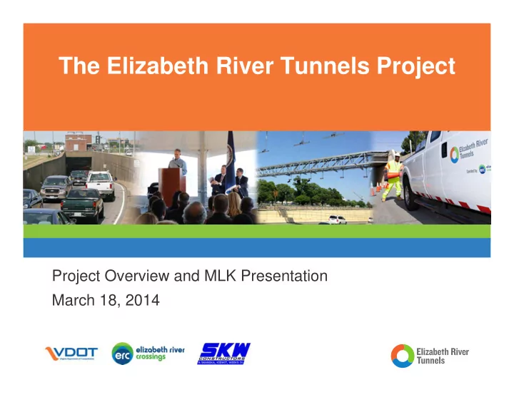
The Elizabeth River Tunnels Project Project Overview and MLK Presentation March 18, 2014 The Design-Build Team Design-Build Joint Venture Skanska USA Civil SE Kiewit Infrastructure Company Weeks Marine Design Team Parsons
Design-Build Joint Venture —Skanska USA Civil SE —Kiewit Infrastructure Company —Weeks Marine Design Team —Parsons Brinckerhoff —Volkert & Associates Immersed Tube Tunnel Experience: —Since 1964, installed 74% of the ITT’s in the USA —Installed 52,500 feet in the USA —19,700 feet of ITT in the Norfolk Area
2
3
Timetable
Call for conceptual proposals May 2008 Conceptual proposal submittal September 2008 Public Hearings – Independent Review Panel March to June 2009 Positive CTB Recommendation July 2009 Key business points presented to CTB October 2009 Signature of Interim Agreement January 2010 IA Phase 1 - Feasibility Stage January 2010 IA Phase 2 - Development Stage June 2010 Signature of Comprehensive Agreement December 2011 Financial Close / Construction Start April 2012
4
5
New Midtown Tunnel Rehab Existing MTT MLK Extension Rehab Existing Downtown Tunnels (EB & WB) Portsmouth Norfolk
6
Concrete shell, Immerse Tube Tunnel (ITT) West bound Tube connecting Norfolk to Portsmouth Two vehicular lanes and an egress corridor
7
Construction in Baltimore due to availability of dry docks Trial Casting — Demonstrate techniques — Test thermal modeling Two Casting Cycles — CC 1 – 6 elements — CC 2 – 5 elements Dimensions (average) — 350’ x 54’ W x 28’ T — 16,000 Tons each
8
Construction in Baltimore due to availability of dry docks Trial Casting — Demonstrate techniques — Test thermal modeling Two Casting Cycles — CC 1 – 6 elements — CC 2 – 5 elements Dimensions (average) — 350’ x 54’ W x 28’ T — 16,000 Tons each
9
10
Each Element constructed in Segments — Inverts (5 per element) — Interior Walls (5 per element) — Roof (Doghouse) (5 per element) Formwork Traveler — Progresses from segment to segment — Moving production line
11
12
13
14
Elements to be immersed into a dredged trench with a screeded gravel base — Approx. max depth of 95 feet
15
Seals between Elements — Gina Joint (gasket type) — Omega Seal (inner connection) Elements to connect to Cast in Place Approach work
16
Seals between Elements — Gina Joint (gasket type) — Omega Seal (inner connection) Elements to connect to Cast in Place Approach work
17
Elements to be immersed into a dredged trench with a screeded gravel base — Approx. max depth of 95 feet
18