? sync ref chosen as sync source by Listener Stream B: - - PowerPoint PPT Presentation

sync ref chosen as sync source by listener stream b
SMART_READER_LITE
LIVE PREVIEW

? sync ref chosen as sync source by Listener Stream B: - - PowerPoint PPT Presentation

Nominal Media Clock: Ts (implicit, not distributed) Stream A: ? sync ref chosen as sync source by Listener Stream B: Presentation Stream C: timestamps Stream D: from different Talkers A-F Stream E: Listener must Stream F: align


slide-1
SLIDE 1

Nominal Media Clock:

(implicit, not distributed)

Stream F: Stream E: Stream D: Stream C: Stream B: Stream A: Presentation timestamps

from different Talkers A-F

Common Timing Grid:

(explicit anchor points )

Stream F: Stream E: Stream D: Stream C: Stream B: Stream A:

?

sync ref

sync window

(arbitrarily chosen by listener)

T ?

sync ref

Listener must align streams (typical case)

chosen as sync source by Listener

sync window

(well known)

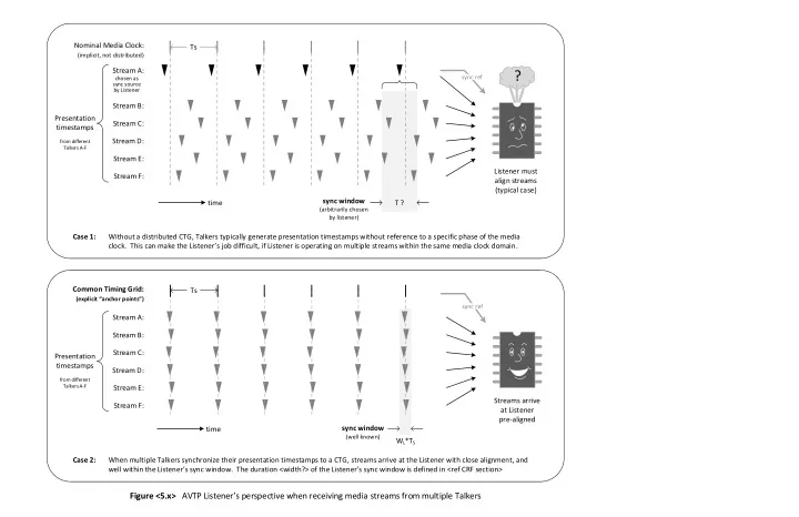
WL*TS Ts Streams arrive at Listener pre-aligned Without a distributed CTG, Talkers typically generate presentation timestamps without reference to a specific phase of the media

  • clock. This can make the Listener s job difficult, if Listener is operating on multiple streams within the same media clock domain.

Ts Case 1: When multiple Talkers synchronize their presentation timestamps to a CTG, streams arrive at the Listener with close alignment, and well within the Listener s sync window. The duration <width?> of the Listener s sync window is defined in <ref CRF section> Case 2: Presentation timestamps

from different Talkers A-F

time time

Figure <5.x> AVTP Listener s perspective when receiving media streams from multiple Talkers

slide-2
SLIDE 2

If CTG is used, must be time aligned with the CTG within a specified window of tolerance (ref CRF section of 1722a)

This implies specifics about implementation (i.e. how stream packets are generated prior to going on the wire) which arguably should be out of scope Suggested Change A Talker shall queue each 1722 stream packet for transmission at a time no later than (PT – MTT), where PT is the presentation time in the current packet and MTT is the Max Transit Time. Application dependent and

  • ut of scope of this standard

Comments on current timing measurement planes diagram in 1722-2011 Question: Is this diagram due for changes or replacement? (not sure.. Discuss..)

slide-3
SLIDE 3

Network Infrastructure

Time-sensitive Application A

AVTP Talker AVTP Listener

AVB/TSN compliant Network Interface Tx queue Rx queue

Time-sensitive Application B

AVTP Talker AVTP Listener

Time-sensitive Application C

AVTP Talker AVTP Listener

Phy

tGQ.A tQP.A

AVB/TSN compliant Network Interface Tx queue Rx queue Phy

tGQ.B tQP.B

AVB/TSN compliant Network Interface Tx queue Rx queue Phy

tGQ.C tQP.C tG.A tP.A tMT.AC tMT.AB tMT.CA tMT.BA tMT.BC tMT.CB tG.B tP.B tG.C tP.C PTOAC tGQ.A + tMT.AC + tQL.C where: tGQ.A = time from sample generated to packet in tx queue for Talker A tMT.AC = max transit time across network from Talker A to Listener C tQL.C = time from rx queue to ready for app consumption for Listener C Stream AC

Example: Calculation of minimum Presentation Time Offset for Stream AC Possible new diagram to help more cleary define and quantify the presentation time offset concept and requirement