
SLIDE 1
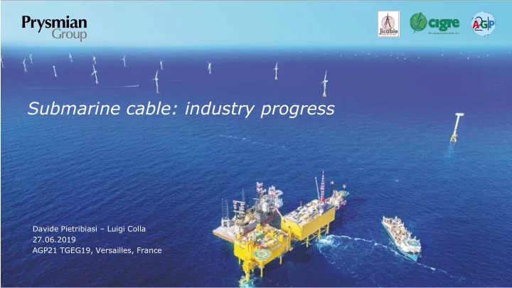
Davide Pietribiasi – Luigi Colla 27.06.2019
Submarine cable: industry progress
AGP21 TGEG19, Versailles, France
Submarine cable: industry progress Davide Pietribiasi Luigi Colla - - PowerPoint PPT Presentation
Submarine cable: industry progress Davide Pietribiasi Luigi Colla 27.06.2019 AGP21 TGEG19, Versailles, France HVDC FOR CABLE INTERCONNECTIONS What will be required? Sources: Forecast demand and manufacturing capacity for HVAC and HVDC
Davide Pietribiasi – Luigi Colla 27.06.2019
AGP21 TGEG19, Versailles, France
2
Sources: Forecast demand and manufacturing capacity for HVAC and HVDC underground and submarine cables, ENTSOE-E/Europacable Electricity transmission of tomorrow underground and subsea cables in Europe, Europacable
3
State-of-the-art cable designs for submarine interconnections
Typically bundled with optical cables, to combine energy and telecom transmission: different types of system configurations (unrepeated, repeated with passive amplifiers, repeated with active amplifiers) depending on link length New generation of cable laying vessels able to match with long installation campaign lengths, minimize number of joints and reduce installation time Monitoring, preventive maintenance and readiness to repair – integrated monitoring in the cable design
4
for land systems
elastomer)
(2500mm2/3500mm2)
Is the future of HVDC for thermoplastic materials?
XLPE
HPTE
5
MANUFACTURING EXPERIENCE
HIGHEST VOLTAGE
with MI
with MI PPL INSTALATION EXPERIENCE
above 400kV
1650m (SAPEI)
740km (NSN) SERVICE EXPERIENCE
above 400kV (Italy- Greece)
WESTERNLINK - UK HVDC ± 600 kV various sizes NSN – UK/NO HVDC ± 515 kV 1800mm2 Cu NEPTUNE - US HVDC + 500 kV 2100mm2 Cu SKAGERRAK4 - DK HVDC ± 525 kV various sizes SAPEI - IT HVDC ± 500 kV various sizes ITALY GREECE – IT/GR HVDC + 400 kV 1250mm2 Cu BASSLINK - AU HVDC + 400 kV 1250mm2 Cu
6
Sources: Windenergy, 2017; Policy paper “Offshore wind Sector Deal” by UK Department for Business, Energy & Industrial Strategy
7
CONSOLIDATED CABLE DESIGN FOR SUBMARINE SECTION Copper conductor XLPE based insulation for 320kV Lead sheated Single wire armoured (shallow waters) Cross section transitions CONSOLIDATED CABLE DESIGN FOR LAND SECTION Aluminium conductor XLPE based insulation for 320kV Welded aluminium sheated
8
MANUFACTURING EXPERIENCE
INSTALLATION EXPERIENCE
connecting HVDC offshore windfarms
between offshore and onshore POWER
submarine cable
9
1. Up to 2GW power for each windfarm connection Requires qualifications up to 525kV and cross sections >2500mm2 2. System solutions System optimization since tendering phase, exploiting benefits of integrated supply&installation; closer interfaces with converter/platform suppliers 3. Hybrid solutions New windfarm concepts; decreased installation corridors 4. Security of the power supply System redundancy/backups, cable requirements in case of multiterminal systems, revision of insulation coordination requirements (CIGRE dedicated WGs)
10 Presentation title | Client’s name or Subtitle | DD Month Year
CHARACTERISTICS MV THREE CORE HV THREE CORE HV SINGLE CORE Insulation
EPR or XLPE XLPE XLPE Self Contained Fluid Filled
Maximum voltage
72.5 kV 245 kV 420 kV 525 kV
Maximum power per circuit
90 MVA 400 MVA 1000÷1200 MVA 1200 MVA
Maximum length
Not limited by cable technology Not limited by cable technology Not limited by cable technology ~ 60 km due to hydraulic system limits
NOTE 1: Submarine cables may have different armouring design mainly depending on water depth NOTE 2: rating depends on ambient and installation parameters
11 Presentation title | Client’s name or Subtitle | DD Month Year
12
13
14
15
Tunnel Seabed Sea/Land joints Cable/OHL transition station Cable/OHL transition station
0.6 km
AC
Overhead line Overhead line
AC
400 kV network 400 kV network
0.1 km
Sea/Land joints
https://www.windpoweroffshore.com/article/1497569/fir st-power-kincardine-floating-project
https://www.sbmoffshore.com/wpcontent/uploads/2 013/09/SBM-Offshore-wind-floater.jpg