study on air ingress processes during a depressurization
play

STUDY ON AIR INGRESS PROCESSES DURING A DEPRESSURIZATION ACCIDENT OF - PowerPoint PPT Presentation

National university corporation Back ground and objective UNIVERSITY OF YAMANASHI The objective of this study are to research gas mixing process and to develop the prevention technology of air ingress. STUDY ON AIR INGRESS PROCESSES DURING A


  1. National university corporation Back ground and objective UNIVERSITY OF YAMANASHI The objective of this study are to research gas mixing process and to develop the prevention technology of air ingress. STUDY ON AIR INGRESS PROCESSES DURING A DEPRESSURIZATION ACCIDENT OF VHTR It is necessary to prevent air Ingress or oxidation of graphite at pipe rupture accident of Very High Temperature Reactor. Contents Even if the pipe rupture accident occurs, ingress of air can 1. Introduction prevent by injecting helium gas. 2. Experimental apparatus and numerical model 3. Experimental and numerical results and discussion Air ingress scenario in the case of the horizontal pipe break 4. Conclusions 1. Pipe rupture at connecting pipe between RPV and gas turbine. 2. Helium gas blows off from the RPV. Tetsuaki TAKEDA 3. Pressure in the reactor equalized to the one in the containment or confinement vessel. Graduate School of Engineering. Dept. of Mechanical Engineering 4. Buoyancy force produce by the temperature difference between inside and outside passage in the RPV. University of Yamanashi 5. Natural circulation of air will produce. (depend on temperature profile or geometrical condition) International Conference on High Temperature Reactor Technology HTR 2018, 6. Graphite of reactor component will react with ingress air. Schematic diagram of GTHTR300C October 8-10, 2018, Warsaw, Poland Designed by JAEA 2 International Conference on High Temperature Reactor Technology, HTR 2018, Oct. 8-10, 2018, Warsaw, Poland, HTR2018-180 International Conference on High Temperature Reactor Technology, HTR 2018, Oct. 8-10, 2018, Warsaw, Poland, HTR2018-180 
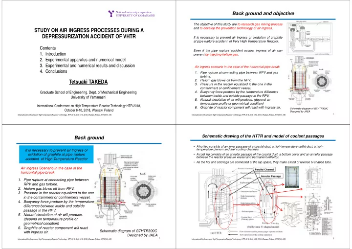
Schematic drawing of the HTTR and model of coolant passages Back ground • A hot leg consists of an inner passage of a coaxial duct, a high-temperature outlet duct, a high- temperature plenum and fuel cooling channels. It is necessary to prevent air Ingress or oxidation of graphite at pipe rupture • A cold leg consists of an annular passage of the coaxial duct, a bottom cover and an annular passage between the reactor pressure vessel and permanent reflector. accident of High Temperature Reactor • As the hot and cold legs are connected at the top space, they make a kind of reverse U-shaped tube. Air Ingress Scenario in the case of the horizontal pipe break 1. Pipe rupture at connecting pipe between RPV and gas turbine. 2. Helium gas blows off from RPV. 3. Pressure in the reactor equalized to the one in the containment or confinement vessel. 4. Buoyancy force produce by the temperature difference between inside and outside passage in the RPV. 5. Natural circulation of air will produce. (depend on temperature profile or geometrical condition) 6. Graphite of reactor component will react Schematic diagram of GTHTR300C with ingress air. Designed by JAEA 3 4 International Conference on High Temperature Reactor Technology, HTR 2018, Oct. 8-10, 2018, Warsaw, Poland, HTR2018-180 International Conference on High Temperature Reactor Technology, HTR 2018, Oct. 8-10, 2018, Warsaw, Poland, HTR2018-180

  2. Schematic drawing of the GTHTR300C and model of coolant passages Influence that localized natural convection in the vertical channels with different temperature exerts on onset time of natural circulation The experiment has been carried out to research mixing process of two component gases and onset time of natural circulation of air. Light gas When one side wall is heated and the other side wall is cooled in a vertical slot, a localized natural convection is generated. Heavy gas will diffuse into the both vertical slots at the same time, and then time elapsed, Heavy gas natural circulation through the passage will be generated finally. Molecular diffusion Purpose of this study To investigate an onset time of natural The flow regime of this localized circulation and a mixing process of two natural convection is ranging from component gases by using 3D numerical conduction regime to boundary analysis. layer regime. 5 6 International Conference on High Temperature Reactor Technology, HTR 2018, Oct. 8-10, 2018, Warsaw, Poland, HTR2018-180 International Conference on High Temperature Reactor Technology, HTR 2018, Oct. 8-10, 2018, Warsaw, Poland, HTR2018-180 Experimental procedure Experimental apparatus  The apparatus consists of two vertical slots, 1. Heavy gas is filled with apparatus. connecting passage and storage tank.  Vertical slots and storage tank were 2. Partition plate close. separated by partition plate. 3. Light gas inject from top of the  The left side vertical slot consists of a heated apparatus. wall and a cooled wall. 4. Two vertical wall of the left hand  The right side vertical slot consists of two side slot is heated and cooled. cooled walls. 5. When the steady state was Light gas established, the partition plate open. 6. Experiment starts. Heavy gas 7 8 International Conference on High Temperature Reactor Technology, HTR 2018, Oct. 8-10, 2018, Warsaw, Poland, HTR2018-180 International Conference on High Temperature Reactor Technology, HTR 2018, Oct. 8-10, 2018, Warsaw, Poland, HTR2018-180

  3. Numerical model Numerical model PHOENICS : three ‐ dimensional CFD code PHOENICS: three-dimensional CFD code  Analytical domain  Analytical domain X : 548, Y : 398, Z : 846 mm X : 548, Y : 398, Z : 846 mm  Analytical grid  Analytical grid x: 122, y: 20, z: 118 (total cells : 266680) x: 122, y: 20, z: 118 (total cells : 266680)  Boundary condition  Boundary condition Z The outside of the heated The outside of the heated wall and the wall and the cooled wall Z cooled wall assumed an adiabatic wall. assumed an adiabatic wall. X The other walls assumed natural The other walls assumed X natural convection heat convection heat transfer boundary transfer boundary condition. condition.  Others  Others Standard density : ρ 0 Standard density : ρ 0  Buoyancy : ( ρ - ρ 0 )gV → Buoyancy : ( ρ - ρ 0 ) gV 9 10 International Conference on High Temperature Reactor Technology, HTR 2018, Oct. 8-10, 2018, Warsaw, Poland, HTR2018-180 International Conference on High Temperature Reactor Technology, HTR 2018, Oct. 8-10, 2018, Warsaw, Poland, HTR2018-180 Numerical method Two component gases and temperature difference  Numerical method: Gases Density [kg/m 3 ] (20ºC, 1atm) 1. Steady state calculation: Natural convection was generated by Helium (He) 0.164 temperature difference between the vertical walls. Neon (Ne) 0.838 2. Unsteady state calculation: Partition plate was opened at 0 sec. Nitrogen (N 2 ) 1.17 Calculation step : 0.01sec/step ・・・ 0~10sec 0.05sec/step ・・・ 10sec~ Argon (Ar) 1.64  Initial condition of steady state: Heavier and lighter gases were filled. Two component gases Diffusion coefficient The vertical walls of the left side slot was (light-heavy) [cm 2 /s] heated and cooled. N 2 -Ar 0.20  Initial condition of unsteady state: Ne-Ar 0.32 The result obtained by steady state calculation. He-N 2 0.68 He-Ar 0.73 Two component gases Diffusion coefficient Gases Density [kg/m 3 ] (20ºC, 1atm) [cm 2 /s] (light-heavy) Helium (He) 0.164 N 2 -Ar 0.20 Temperature difference between wall [K] Neon (Ne) 0.838 Ne-Ar 0.32 30 , 50 , 70 , 100 Nitrogen (N2) 1.17 He-N 2 0.68 Argon (Ar) 1.64 He-Ar 0.73 11 12 International Conference on High Temperature Reactor Technology, HTR 2018, Oct. 8-10, 2018, Warsaw, Poland, HTR2018-180 International Conference on High Temperature Reactor Technology, HTR 2018, Oct. 8-10, 2018, Warsaw, Poland, HTR2018-180

  4. Numerical result (change of gas temperature) Numerical result (change of gas temperature) Z[mm] Z[mm] (1) (10) 50 (2) 50 200 (3) 50 (4) 50 (5) (11) 50 (6) 50 (7) 200 50 (8) 50 (9) (12) Z 90 Z[mm] 75 Z[mm] (He-Ar, Δ T=100K) (He-Ar, Δ T=100K) 13 14 International Conference on High Temperature Reactor Technology, HTR 2018, Oct. 8-10, 2018, Warsaw, Poland, HTR2018-180 International Conference on High Temperature Reactor Technology, HTR 2018, Oct. 8-10, 2018, Warsaw, Poland, HTR2018-180 Numerical result (change of velocity) Comparison between experiment and numerical analysis experiment numerical analysis Z[mm] X Z[mm] Z[mm] 15 ℃ 5 ℃ Z[mm] Z[mm] (He-Ar, Δ T=100K) (He-Ar, Δ T=100K) 15 16 International Conference on High Temperature Reactor Technology, HTR 2018, Oct. 8-10, 2018, Warsaw, Poland, HTR2018-180 International Conference on High Temperature Reactor Technology, HTR 2018, Oct. 8-10, 2018, Warsaw, Poland, HTR2018-180

Download Presentation
Download Policy: The content available on the website is offered to you 'AS IS' for your personal information and use only. It cannot be commercialized, licensed, or distributed on other websites without prior consent from the author. To download a presentation, simply click this link. If you encounter any difficulties during the download process, it's possible that the publisher has removed the file from their server.

Recommend


More recommend