The HTMR100 Modular High Temperature Gas Reactor program 1 - - PowerPoint PPT Presentation

the htmr100 modular high temperature
SMART_READER_LITE
LIVE PREVIEW

The HTMR100 Modular High Temperature Gas Reactor program 1 - - PowerPoint PPT Presentation

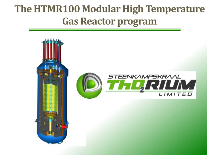
The HTMR100 Modular High Temperature Gas Reactor program 1 Plant overview HTMR100 Reactor The HTMR100 is a 100MW th helium cooled power plant The heat source is based on pebble bed technology which has intrinsic safety


slide-1
SLIDE 1

The HTMR100 Modular High Temperature Gas Reactor program

slide-2
SLIDE 2

1 Plant overview

slide-3
SLIDE 3

HTMR100 Reactor

  • The HTMR100 is a 100MWth helium cooled power plant
  • The heat source is based on pebble bed technology

which has intrinsic safety characteristics

  • Power conversion is via a proven helical coil steam

generator.

  • The HTMR100 is a CO2-free nuclear thermal power

source that can be utilised for power generation, process heat applications, water desalination and hydrogen production.

  • Small size and modular construction result in relatively

low cost.

slide-4
SLIDE 4

HTMR100 Reactor

Reflector rod drive mechanism Bottom access hatch Top access hatch Top reflector Control rod Reactor pressure vessel (RPV) Side reflector Bottom reflector Spent fuel outlet shute Hot gas outlet Core barrel

slide-5
SLIDE 5

Plant Layout (Single Module)

1 2 3 4 5 6 7 8 9 10 11 12 13 14 15 16

1 Reactor building 9 Concrete vessel manufacturing 2 Auxiliary building 10 Emergency control building 3 Electrical building 11 Entrance control building 4 Turbine hall 12 Admin building 5 Conventional cooling 13 Store 6 Secured cooling 14 Radioactive waste treatment facility 7 Water storage tanks 15 Parking 8 Spent fuel storage area 16 Laydown area

slide-6
SLIDE 6

Plant Layout (Multi Module)

slide-7
SLIDE 7

Plant Layout (Multi Module) ; Sub-ground level

slide-8
SLIDE 8

Thorium Fuel

slide-9
SLIDE 9

2 Technology Basis

slide-10
SLIDE 10

Technology Basis

HTR-10 (China) HTTR-30 (Japan)

HTMR-100 SA

HTR-PM (China)

slide-11
SLIDE 11

3 Safety Design Basis

slide-12
SLIDE 12

Safety Design Approach

  • 1. No Active Nuclear Safety Related Systems. The plant

does not rely on active safety related systems during design basis accidents

  • 2. Passivity by activation /de-activation e.g.
  • pen/close of a nuclear safety related valve.
  • 3. Passive product and structures will not fail during

events it is designed for. Examples are concrete structures, piping, graphite structures , vessels etc designed for earthquakes

  • 4. Avoid high temperature gas on metallic structures,

keep the high temperature gas in the graphite structures.

slide-13
SLIDE 13

Safety Design Basis

Plant Nuclear Safety

  • The plant has no active safety related fluid system to mitigate the effect
  • f an accident.
  • The reactor protection system with its backup batteries, input signals and
  • utput action are safety-related . Actions are basically by valves. The plant

ensure safety through ‘passive-by-activation ‘ means .

  • Emergency diesel-generators are non-safety related, no credit for its

function during postulated design basis accidents and external events.

  • Residual heat removal is by natural means with active secured cooling

system backup and emergency connecting point (electric and water)

  • The safety-related functions are grouped into a compact reactor building

which can be constructed at different ground elevations. Sub-ground level protects against large airplane crash.

slide-14
SLIDE 14

Safety Design Basis Continue

Reactor & Primary loop intrinsic safety

  • Neutronically safe achieved through:
  • Strong negative temperature coefficient which

means the reactor automatically shuts down in loss of coolant event.

  • Weak fission product transport mechanism :
  • helium is inert and is not activated,
  • dust is periodically removed,
  • He is continually purified.
  • No primary coolant phase change and low/slow

pressure buildup with energy addition.

  • No possible buildup of explosive hydrogen mixtures.
  • No secured core cooling required; low power density,

large mass to absorb energy, slender geometry to transfer residual heat by passive means

slide-15
SLIDE 15

4 HTMR100 Reactor

slide-16
SLIDE 16

HTMR100 Reactor

Reflector rod drive mechanism Bottom access hatch Top access hatch Top reflector Control rod Reactor pressure vessel (RPV) Side reflector Bottom reflector Spent fuel outlet shute Hot gas outlet Core barrel

Power 100MW Pressure 40 bar Reactor Outlet Temperature 750 °C Power Conversion Steam Cycle Product Heat and/or Electricity

slide-17
SLIDE 17

HTMR100 Reactor

  • The advantage of smaller size is that the reactor and all

components and systems can be constructed modularly and shipped to site for assembly.

  • Cost of scale is overcome by mass production with a

high degree of factory assembly.

slide-18
SLIDE 18

HTMR100 Reactor

CRDMs Control rod connecting tubes Core internals Reactor pressure vessel

slide-19
SLIDE 19

Reactor pressure vessel

slide-20
SLIDE 20

Transportability by road

slide-21
SLIDE 21

5 Steam Generator

slide-22
SLIDE 22

Steam Generator

Reactor Unit (RU) Steam Generator Unit (SGU) Reactor pressure vessel (RPV) Reflector rod Drive mechanism (x16) Core unloading Machine (CUM) (x2) Blowers (x2) Steam outlet (x3) Feedwater inlet (x3) Connecting vessel Unit RPV support (x3)

slide-23
SLIDE 23

6 Core Structures

slide-24
SLIDE 24

Core structures

  • Manufacturing is modularised
  • Pressure vessel first installed
  • Core Structures are

assembled in a factory and shipped in 3 modules including instrumentation harnesses.

Module 3 Module 2 Module 1

slide-25
SLIDE 25

Ceramic Core

Graphite core structures Complete assembly Upper core structures Bottom core structures

slide-26
SLIDE 26

7 Power Conversion System

slide-27
SLIDE 27

Power Conversion System

Design philosophy

  • The design philosophy of the power conversion system (PCS) is the following:
  • Proven and widely used industrial technology should be used
  • Off-the-shelf components should be chosen as far as possible

The chosen technology should have a relatively short installation time and require minimal maintenance

slide-28
SLIDE 28

Power Conversion System without condenser

Steam Generator Gearbox Unit Steam Turbine

slide-29
SLIDE 29

8 Fuelling Scheme

slide-30
SLIDE 30

Fuelling Scheme

slide-31
SLIDE 31

9 Buildings

slide-32
SLIDE 32

Crane Reflector rod drive mechanisms Reactor unit unit Citadel Steam generator Spent fuel cask Core unloading Machine (CUM)

Reactor Building

slide-33
SLIDE 33

Electrical building

HVAC floor Control room Conference room Computer room Entrance Electrical distribution floor Security Emergency diesel generators (x2) C & I floor Switchgear Ablution facilities

slide-34
SLIDE 34

Auxiliary building

Chimney HVAC Floor He Purification and dispatch floor Health physics floor Bridge to reactor building Fresh and spent fuel transfer tunnel Waste processing basement

slide-35
SLIDE 35

Reactor Building and Connecting Buildings

slide-36
SLIDE 36

Reactor Building Coupled to the Turbine Building