Structure of Presentation Introduction Challenges in the - - PDF document

structure of presentation
SMART_READER_LITE
LIVE PREVIEW

Structure of Presentation Introduction Challenges in the - - PDF document

Structure of Presentation Introduction Challenges in the Verification of Challenge 1: Variety of modeling languages Electronic Control Units Challenge 2: Learning curve for Requirement Capture Challenge 3: Integration with


slide-1
SLIDE 1

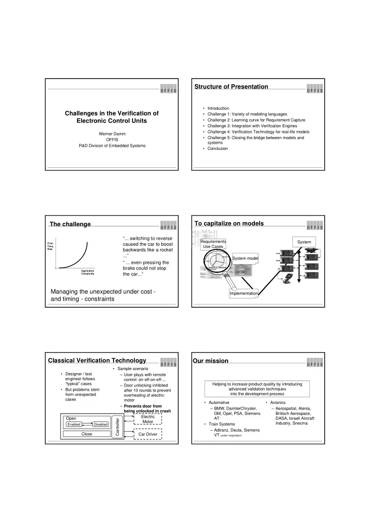
Challenges in the Verification of Electronic Control Units

Werner Damm OFFIS R&D Division of Embedded Systems

Structure of Presentation

  • Introduction
  • Challenge 1: Variety of modeling languages
  • Challenge 2: Learning curve for Requirement Capture
  • Challenge 3: Integration with Verification Engines
  • Challenge 4: Verification Technology for real-life models
  • Challenge 5: Closing the bridge between models and

systems

  • Conclusion

The challenge

“... switching to reverse caused the car to boost backwards like a rocket ...” “ ... even pressing the brake could not stop the car...”

Cost, Time, Risk Application Complexity

Managing the unexpected under cost - and timing - constraints To capitalize on models

System System model Requirements Use Cases Implementation

Analysis Modeling Test Iterative Prototype *

Classical Verification Technology

  • Designer / test

engineer follows “typical” cases

  • But problems stem

from unexpected cases

  • Sample scenario

– User plays with remote control: on-off-on-off-... – Door unlocking inhibited after 10 rounds to prevent

  • verheating of electric

motor – Prevents door from being unlocked in crash Electric Motor Car Driver Close

Enabled Disabled

Open Controller

Our mission

  • Automotive

– BMW, DaimlerChrysler, GM, Opel, PSA, Siemens AT

  • Train Systems

– Adtranz, Deuta, Siemens VT under negotiation

  • Avionics

– Aerospatial, Alenia, Britisch Aerospace, DASA, Israeli Aircraft Industry, Snecma Helping to increase product quality by introducing advanced validation techniques into the development process

slide-2
SLIDE 2

Model Checker

Advanced Verification Technology I

Requirements Use Cases System model Implementation

  • Extremely large state

spaces can be analyzed completely in minutes – For all combination of inputs – For all sequences of combination of inputs

  • 100% coverage with respect

to requirements

  • Creates “golden device” /

reference model Model Checker formally proves consistency of Requirements and System model

Advanced Verification Technology II

Implementation Requirements Use Cases

Golden Device

ATG - Automatic Testvector Generation:

  • input
  • expected output

About FV

  • The maturity level of the system

development process is highly dependent on the application domain

  • focus of this work:

– automotive – avionics – train systems

  • all hard real time
  • all have safety critical

subsystems

  • Process maturity level in

avionics extremely high

  • SW quality is a process issue

– FV covers only very tiny fraction of SW development process – disturbances caused by introducing FV may easily

  • utweigh potential benefits

FV must be subordinate to general process considerations FV must be interfaced with industry standard design tools

Challenge 1

Variety of modeling languages

About FM

  • Wrong:

force developers to learn formal methods

  • Right:

make industry standard design tools formal

  • Case Tools used today in

automotive - avionics - train systems

– Mathlab/Simulink + Stateflow – MatrixX + Better State – STATEMATE – SCADE – ASCET – Rhapsody in MicroC – Titus – ObjectGeode (SDL) – Rhapsody in C++ (UML) – Telelogic Tau Suite

Design Views supported by STATEMATE

slide-3
SLIDE 3

STATEMATE

  • Industry standard case tool

marketed by I-Logix Inc

  • Activity Charts

– System Architecture – Information Flow – Environment

  • State Charts

– visual real-time programming language – hierarchy – orthogonal states – algorithms

  • Animation
  • Simulation
  • RP code generation
  • documentation
  • Widely used in automotive and

avionics, increasing usage in train-systems

SCADE - Safety Critical Application Development

Environment

Synchronous data flow language for specification and design of Reactive Real Time systems (Graphical Frontend for LUSTRE)

Features:

·

Editors ( dataflow, state-machine,...)

·

Simulator

·

Code Generator for C and ADA

·

Document Generator

Design Views Supported in Rhapsody Design Views Supported by Object Geode Problems

  • Even within one front-end tool no or underspecified

relation between multiple views

– e.g. relation between scenarios and behavioural model

  • Even within one modeling style different semantics

between different implementations

– e.g. the 100+x semantics of statecharts

  • Even within one view in one tool underspecification

– e.g. handling of deferred events in UML

  • Even within one view in one tool differences between

simulation semantics and code generation semantics

– e.g. timeouts

Problems (cont.)

  • Real life applications typically require multiple tools

– e.g. hybrid controllers expressed in Statemate and MatrixX – e.g. plant model in Matlab/Simulink and controller model in Statemate – e.g. specification model in Matlab/Simulink, code generation using Scade – e.g. specification model in Statemate and design in UML tool

  • Today only limited support even for co-simulation

– e.g. detecting when plant state should trigger discrete transition

  • Need to give semantic foundation to such combinations

– e.g. hybrid automata

slide-4
SLIDE 4

Lines of Attack

  • Deep background in formal semantics is a must
  • Deep understanding of actual tool usage is a must

– focus on widely used modeling features – let designers point to weak aspects of modeling tool – let designers report on ambiguities

  • Deep cooperation with tool developers is a must
  • Develop reference semantics
  • validate with tool provider
  • validate with designers

SMI/SSL Model-compilation Verification evidence Test-bench C Synth. VHDL Verification Test generation Synthesis Compile / instrument Requirement-compilation TBA SMI

Statemate, Rhapsody in C++ Scade, Stateflow, ASCET VHDL Sequence Charts Timing Diagrams

An active object model

Giving meaning to UML joint work with Bernhard Josko and Amir Pnueli

Anticipated application scenario

  • Distributed implementation on network of ECUs
  • Task: one active object grouped with a collection of

passive objects

  • intertask communication typically asynchronous
  • operation calls used for intertask communication to

bypass event queue, expected to be infrequent

  • calls to primitive operations are executed in same thread

Model characteristics

  • Single thread of control in each

active object – complete serialization of incoming operation calls and events – required to enhance understandability and verifiability – hence support only protected

  • peration calls to triggered
  • perations
  • each active objects comes

equipped with – event queue – queue of pending operation calls

  • run-to-completion semantics

– dispatch single event from event queue – evaluate state chart until stable configuration is reached

  • design decision: level of

interference – can higher priority calls preempt ongoing run to completion steps? – tradeoff between model complexity and enhanced responsiveness – will explore both variants

Design issues

  • The driver role

– object stable

  • rests in piece
  • waiting for work

– picks event from event queue – thus triggering a new run-to- completion step – invoking operation calls – driving its run-to-completion

  • The callee role

– object executes operation call

  • n behalf of some other object

– helping some other guy to complete its run-to-completion step

  • When do we allow objects to

switch from driver to callee role?

  • How do we decide whether to

dispatch a new event or to take a call?

  • Ready_Set of configuration:

– set of events and operation call

  • ccurring as guards in

potentially enabled transitions

  • What happens if selected
  • peration call is not in ready

set?

  • What happens if dispatched

event is not in ready set?

slide-5
SLIDE 5

Design decisions coarse grained model

  • No preemption of run to

completion steps – new events or calls only taken in stable configurations

  • event dispatching strictly in

FIFO order – dispatched events not in ready set placed in “defer queue”

  • selection policy purely based
  • n priorities, random choice in

case of ties

  • selected operations not in

ready set return error value

Event _queue empty no stable Process a transition Dispatch event No locally enabled transition Accept method call Locally enabled transition

Status Active Object Model

  • Formal semantics of Active Object model

– addressing communication between multiple active objects – deals with

  • events
  • primitive operations
  • triggered operations
  • protected operations
  • UML statecharts
  • dynamic object creation and deletion
  • reference for ongoing integration of Rhapsody execution

model

  • supports modeling of open systems

Challenge 2

Learning curve for Requirement Capture

Issues

  • No penetration of formal methods if learning curve is too

high

  • Writing requirements in formal logic only acceptable for

specialists

  • Need to mock-up concepts familiar to designers

– watchdogs – timing diagrams – scenarios – witnesses: can I reach a state, can I toggle an output, ... – pure invariance properties – predefined properties: no deadlock, no racing conditions, ... – Libraries of paramatrized requirements: protocols, domain specific, ... Safety Requirements

Supporting Views

1.Für einen Bahnübergang kann nur eine Anforderung von einem Zug kommen, in dessen zugewiesenen Fahrweg der Bahnübergang liegt. 2.Bei einem eingleisigen Bahnübergang kann zu einem Zeitpunkt nur eine Anforderung vorliegen. 3.Ein Bahnübergang darf nur befahren werden, wenn er die Stellanweisung quittiert hat (entspricht fernüberwachtem BÜ) oder der Zug die Meldung über die ordnungsgemäße Sicherung vom Bahnübergang erhalten hat (entspricht ÜS bzw. Hp). 4.Vor Erreichen des Bremswegabstands vom Bahnübergang muss der Zug die Meldung über die erfolgte Sicherung des Bahnübergangs oder die Quittierung der Anforderung zur Sicherung (entspricht FÜ) erhalten haben, sonst muss er eine Bremsung entsprechend der zuvor berechneten Bremskurve einleiten. 5.Wenn ein technisch gesicherter Bahnübergang auf die Anweisung von einem Zug nicht reagiert (antwortet), muss der Zug vor dem Bahnübergang zum Halten kommen. 6.Die Sicherung eines Bahnübergangs darf erst wieder aufgehoben werden, wenn der Bahnübergang vom Zug befahren und vollständig geräumt wurde oder der Zug die Anforderung zurücknimmt. 7.Die Sicherung eines mehrgleisigen Bahnübergangs darf nur aufgehoben werden, wenn keine Anforderung eines weiteren Zuges, der innerhalb der maximal zulässigen Annäherungszeit am Bahnübergang eintrifft, vorliegt. 8.Bei einer Zeitüberschreitung kann die Sicherung eines Bahnübergangs nur von der FFB-Zentrale aufgehoben werden. 9.Eine Zeitüberschreitung muss der FFB-Zentrale mitgeteilt werden. 10.Bei einer Dauereinschaltung kann die Sicherung eines Bahnübergangs nur von der FFB-Zentrale aufgehoben werden.

A train may only pass a crossing if it is secured The barrier may only be

  • pened after the train

has passed the crossing

Timing Diagrams

  • graphical entry for safety,

functional and real-time requirements

  • library of typical requirement

patterns

alarm safe [10,50]

  • functional test can be

generated from STDs

  • specification models can

be verified against STDs

  • sample safety requirements:

– never allow to open car when driving – never release weapon when on ground – when engine control switches to manual, all valves must be

  • pen

– the airbag must be blown up 5ms following an impact – a train may only pass a crossing if it is secured

slide-6
SLIDE 6

A sample safety requirement ... and its formalization

A train may

  • nly pass a

crossing if it is secured

Activation Condition Condition on interface variables Events Ordering or timing constraint System Architecture

Supporting Views Limitations of MSCs

  • What MSCs say

– which instances – possible scenarios – possible communication

  • partial order on visible

events

  • ... and can´t say

– in this use case the system must follow the scenario – the instance will sent the message – the message will arrive – no other message will be sent in between – failure to meet condition is fatal

Activation Condition Ordering required Failure to meet condition is error solid instance lines entail progress requirements Real time requirements

Live Sequence Charts

  • LSCs allow designers to distinguish between mandatory

and possible behaviour

– cold conditions provide exit mechanism,allow to split cases into separate subcharts – hot conditions allow to express forbidden situations – existential charts show possible behaviour – universal charts must be observed by all runs of the system – activation conditions and precharts allow to characterize situations when universal charts apply

Joint work with David Harel, Weizmann Institut of Sciences

functional test can be generated from LSCs specification models can be verified against LSCs

Challenge 4

Verification Technology for real-life models

slide-7
SLIDE 7

Formal Verification

  • Formal verification techniques on the edge of becoming

accepted in real time / safety-critical embedded system domains

– automotive, avionics, train systems, telecommunication, ...

  • Pre-requisite

– increasing level of process maturity – model based process

  • FV seen to reduce time to market and cost
  • FV seen as an enabler in the certification process

Problems

  • Fully automatic approaches must be capable of coping

with “natural” design units

– complete “simple” ECUs in automotive – key functionality of complex ECUs/LRUs

  • real life models are infinite state

– floats, unbounded integers, parametrization, ...

  • Verification technologies only useful if diagnostic

information can be lifted back to original modeling language

– must be able to show reasons why requirement not fulfilled

Lines of attack

  • Need plurality of verification

techniques

  • ptimize for different use cases

– try to avoid full exploration of state space

  • debugging: try to find faults

– employ under-approximation – optimize verification heuristics for early error detection – ex1: VIS invariance checking mode – ex2: bounded model checking

  • employ both BDD-based and

SAT based verification engines

  • certification: verify safety

properties – use over-approximation – use inductive reasoning – use heuristics for constructing invariants

  • support component based

designs

  • support large scale verification

by reasoning on properties of components of design

  • support overall verification task

management

Model Checking of Hybrid Controllers

  • J. Bohn, T. Bienmüller, H. Brinkmann, W. Damm, H. Hungar

OFFIS O.Grumberg Technion

ECU Implementation

ECU StateMate MatrixX

@alpha

Master Module

+

Slave Modules E n v i r

  • n

m e n t

Scope of the Method

ECU continuous discrete

Testing First-Order MC Model Checking history bounded continuous computations

slide-8
SLIDE 8

LEVEL ALARM VALVE SENSOR

Controller Controled System Operator

Level Sampling rate determined LEVEL ALARM VALVE SENSOR

Controller Controled System Operator

Level If the level grows too fast within two cycles, then set ALARM within one cycle ALARM WATCH DOG LEVEL LEVEL-x > th = x TRUE <=2 <=1 LEVEL ALARM VALVE SENSOR

Controller Controled System Operator

Level N O A C LEVEL_OLD LEVEL Combinational Logic MX STM c1 c2 c3 c5 c6 c4 cj ≡ LEVEL_OLD - LEVEL >/< thj LEVEL = LEVEL_OLD

f

ECU Operation

level = f(level,sensor,valve) valve = . . . b(level) . . . alarm = . . . th(level - level_old) . . . level_old = level . . . level

continuous discrete step main loop

Property Dependence

step n-1 step n step n+1 step n+2 step n+2 level = x level-x > th alarm = true

window length 3

Essential: number of relevant continuous computations bounded inside window

Finite length implies bounded number

  • f computations

Realization I

  • 1st order Modelchecker

– user determines which data-items are to be treated symbolically – BDD based – computes on the fly codenames for substitution instances of all relevant propositions

  • finite window property only necessary for property driven elaboration

degree – “1st-order BDD engine” to deal with e.g. existential quantification – automatic constraint generation for codenames – prototype available – implementation as extension of VIS scheduled jointly with Fabio Somenzi

slide-9
SLIDE 9

Realization II

  • Discrete

– preprocesser on SMI level:

  • can be used in conjunction with both standard BDD-based and SAT

based engines

  • can be used for debugging and certification

– replaces computations on floats by codenames for relevant properties on SMI level – restricted to linear computations on floats with bounded memory – concretization of error path uses linear constraint solver – ongoing evaluation

Industrial Application (BMW)

Break Management System

MatrixX StateMate

@alpha

Master Module

+

Slave Modules

C a r

thresholds and simple functions on continuous values ⇒ simple version of first-order MC applicable

Comparison FoMC vs manual abstraction BMW application

  • MANUAL

AUTOMATIC ABSTRACTIONS &3-GEN+S "$$.ODES+ &3-STATEBITS &3-INPUTS MODELCHECKINGS

Verification support at OFFIS

VIS (BDD-based) SAT based engine LINSOLVE+ Error-path reconstruction discrete abstraction elaboration slicing Compositional Reasoning Dependency management Verification manager Model-Checking Engine

ACTIVATE_ CRASH: CS: KLR : KL1 5: CHART_CRASH_ ISIN: buffer CRASHED: ZV_ ZS: FAL TRU FALSE FALSE TRU FALSE TRU FAL TRU FALSE FAL TRUE FALSE TRU FALSE FALSE NOTA BER NOTA FALSE FALSE ← ← ← ← → ←

6)35!,):!4)/./& #/5.4%2%8!-0,% 34!4%-!4% MODELOF35$ 2%15)2%-%.4

LSC/STM Verification Environment

Verification Results Automotive

  • One-sweep

verification

  • under no attack

will steering be locked when ignition is on

  • %-&

%,6 STATEBITS INPUTBITS &3-GENS

  • #TIMES
slide-10
SLIDE 10

Verification Results Avionics

  • One-sweep verification of

SMS using abstraction

  • under no attack will SMS

release weapon without pilot consent

  • STORES

STORES STATEBITS INPUTBITS &3-GENS

  • #TIMES

BAE - Stores Management System

Verification Results Train System

  • 4RAIN0

8ING0 3YSTEM0 STATEBITS ABSSTATEBITS MCTIMES P1 The train only passes secure railway Xings P2 The barrier will only be

  • pened, once the train has

passed the Xing, unless the driver or central maintenance control grants permission Joint work with Adtranz

STATEMATE FV Today

  • Substantial number of industrial

trials on models in – automotive – avionics – train systems

  • PIPP version available from I-

Logix – tight integration with Statemate – robustness checks

  • non determinism
  • racing conditions

– write-write conflicts – read-write conflicts – Easy to use standard analysis:

  • drive to state
  • drive to configuration
  • toggle output
  • drive to property

– optimizations – support for generic activity charts

  • PIPP partnerships with key

automotive companies

  • product marketed by I-Logix

Q2/2001

  • incorporation of LSCs

Challenge 5

Closing the bridge between models and systems

FV & ATG are complimentary

  • Verification of

– functional – safety – timing requirements

  • purely model based

– abstracts from target HW – abstracts from RTOS – only abstract timing

  • complete coverage

– early detection of design errors – early detection of integration errors based on virtual V

  • largely automatic
  • early phases of V
  • Bridge between (verified)

models and real system – unit test – ECU test – subsystem integration test – system integration test

  • Testing can take into account

– real time – distribution – RTOS

  • Test vectors can be generated

automatically

  • ATG can re-use same

requirements and models used for FV

FV ATG

Evaluation results first prototype ATG technology

  • BMW and GM supplied

industrial trials

  • first prototype

– test-sequences can drive simulation model – integration with dSpace HIL environment at BMW

  • state coverage between 75%

and 85% with test- sequences generated in minutes

  • detected critical output that

could not be driven

  • ongoing cooperation with GM

and BMW

Front-End User-Interface Back-End Kernel SMI/ SSL Statemate ATG Kernel Test Vectors Interfacing HIL/SIL Monitor Report Gen. Test Management Test Goal Selection Back animatio n Report/ Error Path LSC Rhapsody ToolX
slide-11
SLIDE 11

Conclusion

  • Range of verification

techniques required to cover full range of industrial applications

– abstraction – bounded MC – BDD based engines – Sat based engines – linear programming – 1st order modelchecking – symmetry reduction – inductive reasoning – system verification based

  • n compositional reasoning
  • Semantic-based integration of

range of commercial front end tools from different vendors

  • Statemate verification

technology in use by early adaptors

  • Product offerings based on

presented technology about to enter market – STM FV Q2/2001

  • looking now for early adaptors

for ATG technology for Statemate and Rhapsody