STRAIN-INSENSITIVE FIBER BRAGG GRATING ULTRASONIC SENSING SYSTEM - - PDF document

strain insensitive fiber bragg grating ultrasonic sensing
SMART_READER_LITE
LIVE PREVIEW

STRAIN-INSENSITIVE FIBER BRAGG GRATING ULTRASONIC SENSING SYSTEM - - PDF document

18 TH INTERNATIONAL CONFERENCE ON COMPOSITE MATERIALS STRAIN-INSENSITIVE FIBER BRAGG GRATING ULTRASONIC SENSING SYSTEM USING FIBER RING LASER H. Tsuda Research Institute of Instrumentation Frontier, AIST, Tsukuba, Japan hiroshi-tsuda@aist.go.jp


slide-1
SLIDE 1

18TH INTERNATIONAL CONFERENCE ON COMPOSITE MATERIALS

1 Introduction Damages in composites, such as matrix cracks, delamination and fiber breakage, may occur as a result of excessive load, fatigue and low-velocity impact, etc. These damages can be inspected by ultrasonic testing. Conventionally, piezoelectric sensors have been employed as transducers and sensors in ultrasonic testing. Recently, fiber Bragg gratings (FBGs) are expected to provide a replacement for traditional piezoelectric ultrasonic sensors, because FBGs are easy to be embedded into composite structures, not susceptible to electromagnetic field, and enable multiplexing [1]. Previously reported FBG ultrasound sensing systems can be classified into two types in terms of light source employed, i.e., laser and broadband light [2]. A system employing a laser where the lasing wavelength is tuned to 50% reflectivity of the FBG permits sensitive ultrasonic detection. However, the ultrasound sensitivity wanes with the change in strain applied to an FBG because strain causes shift in the FBG reflection spectrum. A system with broadband light source incorporating two Fabry- Perot filters can detect ultrasound regardless of strain applied to an FBG. However, the ultrasound sensitivity periodically depends on the Bragg wavelength of the FBG sensor and the system is lack

  • f ultrasonic sensitivity to detect acoustic emissions

[3]. This paper presents a novel FBG ultrasound sensing system using a fiber ring laser. Ultrasound detection

  • f this system proved to be insensitive to strain

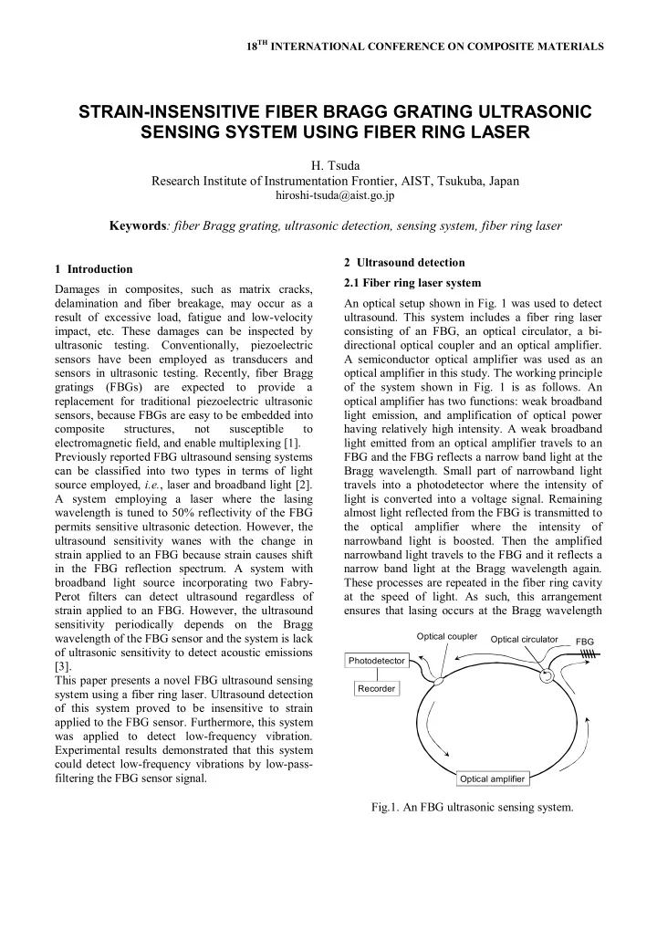
applied to the FBG sensor. Furthermore, this system was applied to detect low-frequency vibration. Experimental results demonstrated that this system could detect low-frequency vibrations by low-pass- filtering the FBG sensor signal. 2 Ultrasound detection 2.1 Fiber ring laser system An optical setup shown in Fig. 1 was used to detect

  • ultrasound. This system includes a fiber ring laser

consisting of an FBG, an optical circulator, a bi- directional optical coupler and an optical amplifier. A semiconductor optical amplifier was used as an

  • ptical amplifier in this study. The working principle
  • f the system shown in Fig. 1 is as follows. An
  • ptical amplifier has two functions: weak broadband

light emission, and amplification of optical power having relatively high intensity. A weak broadband light emitted from an optical amplifier travels to an FBG and the FBG reflects a narrow band light at the Bragg wavelength. Small part of narrowband light travels into a photodetector where the intensity of light is converted into a voltage signal. Remaining almost light reflected from the FBG is transmitted to the optical amplifier where the intensity of narrowband light is boosted. Then the amplified narrowband light travels to the FBG and it reflects a narrow band light at the Bragg wavelength again. These processes are repeated in the fiber ring cavity at the speed of light. As such, this arrangement ensures that lasing occurs at the Bragg wavelength

STRAIN-INSENSITIVE FIBER BRAGG GRATING ULTRASONIC SENSING SYSTEM USING FIBER RING LASER

  • H. Tsuda

Research Institute of Instrumentation Frontier, AIST, Tsukuba, Japan

hiroshi-tsuda@aist.go.jp

Keywords: fiber Bragg grating, ultrasonic detection, sensing system, fiber ring laser

Photodetector Optical amplifier Optical coupler Optical circulator FBG Recorder

Fig.1. An FBG ultrasonic sensing system.

slide-2
SLIDE 2
  • f the FBG.

2.2 Working principle of ultrasound detection The optical gain of an optical amplifier depends on

  • wavelength. Ultrasound impinging on an FBG

results in a minute shift (less than 1 pm) in the Bragg wavelength at which lasing occurs [4]. As a result, the intensity of laser generated from a fiber ring laser varies in accordance with ultrasonic vibration exerting on the FBG. The ultrasound sensitivity of the system is attributed to wavelength dependence of the optical gain in an optical amplifier. The intensity

  • f laser can be measured from a photodetector to

which part of laser light is transmitted [5]. The optical gain depends on wavelength in the whole operating wavelength range of an optical

  • amplifier. Therefore, this system is considered to be

capable of detecting ultrasound regardless of the Bragg wavelength of the FBG sensor, i.e., the system can detect ultrasound regardless of strain applied to the FBG sensor. 2.3 Ultrasound detection using a fiber ring laser system A 10-mm-long FBG with a Bragg wavelength of 1550 nm was bonded on a 1-mm-thick cross-ply CFRP plate and the response to ultrasound propagating on the CFRP plate was recorded. Ultrasound was generated from a piezoelectric ultrasound transmitter whose central wavelength was 250 kHz. The transmitter was put on the CFRP plate 100 mm away from the FBG sensor.

  • Fig. 2 (a) and (b) show the FBG sensor responses to

individual ultrasound pulse excited by a 3-cycle toneburst signal of a frequency of 250 kHz and an impulse signal, respectively. As can be seen from these well-defined responses to individual ultrasound, this system possesses ultrasound sensitivity enough to apply ultrasonic inspection and acoustic emission measurement. 2.4 Ultrasound detection under varying strain condition Ultrasonic responses of an FBG sensor subjected to various strains were recorded using the same experimental setup employed in the previous section. A resistive strain gauge was attached next to the FBG sensor to serve as a strain reference. Ultrasound was excited by a 3-cycle toneburst signal at a frequency of 250 kHz in this experiment.

  • Fig. 3 (a), (b) and (c) show the ultrasonic responses
  • f an FBG sensor subjected to -600 , 0  and 600

, respectively. A well-defined ultrasound response was obtained regardless of strain applied to the FBG

  • sensor. Furthermore, the ultrasonic sensitivity seems

to be independent of strain applied to the FBG sensor.

  • 50

50 100

  • 100
  • 50

50 100

(b)

Response signal, mV Time, s

  • 50

50 100

  • 100
  • 50

50 100 Response signal, mV Time, s

(a)

Fig.2. FBG sensor responses to an individual ultrasound pulse propagating on a cross-ply CFRP

  • plate. Ultrasound excited by (a) a 3-cycle toneburst

signal, (b) an impulse signal.

  • 50

50

  • 50

50

  • 50

50 100

  • 50

50

(a) Response signal, mV (b) Time, s (c)

Fig.3. Ultrasonic responses of an FBG sensor subjected to various strain. Strain (a) at -600 , (b) strain-free, (c) at 600 .

slide-3
SLIDE 3

3 STRAIN-INSENSITIVE FIBER BRAGG GRATING ULTRASONIC SENSING SYSTEM USING FIBER RING LASER

  • Fig. 4 shows the shift in reflection spectrum of the

FBG sensor subjected from -600  to 600 . The strain change shifted the Bragg wavelength by 1.47

  • nm. This system could detect ultrasound despite

considerable shift in the Bragg wavelength. These experiments proved that this system was capable of detecting ultrasound regardless of strain applied to the FBG sensor.

1549 1550 1551 0.0 0.5 1.0 600 Reflectivity Wavelength, nm

  • 600

strain free  = 1.47nm

Fig.4. Shift in reflection spectrum of an FBG sensor in which strain ranged from -600  to 600 . 3 Vibration detection 3.1 Experimental setup The FBG sensor response of the fiber ring laser system to mechanical vibration was investigated. An experimental setup shown in Fig. 5 was used in the

  • test. A 10-mm-long FBG sensor with a Bragg

wavelength of 1550 nm, a resistive strain gauge and a piezoelectric ultrasonic sensor were bonded to a 500 ×50 × 1 mm3 cantilevered cross-ply CFRP

  • plate. A mechanical vibration was given by dropping

a 2.7-gram ceramic ball from a height of 300 mm. The impact point was 200 mm away from the point where the FBG sensor was bonded. Responses of attached sensors were recorded before and after a dropping ball impact. 3.2 Experimental results

  • Fig. 6 shows a 50-kHz-low-pass-filtered FBG sensor

response to impact along with a piezoelectric sensor

  • response. Both sensors had a significant response to

the impact and obvious responses continued for around 15 milliseconds after impact.

FBG sensor Strain gauge Piezo-sensor 200 mm Ceramic ball Free end Fixed end 50 mm 500 mm

Fig.5. Experimental setup for detecting an impact by dropping ball.

  • 20

20 40 60 80

  • 2
  • 1

1 2 Piezo-sensor response, V Time, ms

  • 20

20 40 60 80

  • 1.0
  • 0.5

0.0 0.5 1.0

(b)

Time, ms FBG sensor response, V

(a)

Fig.6. Responses to a dropping ball impact. (a) 50- kHz-low-pass-filtered FBG sensor response and (b) piezoelectric sensor response.

  • Fig. 7 (a) and (b) depict a 100-Hz-low-pass filtered

FBG sensor response and strain curve measured with a strain gauge, respectively. Both sensor responses showed a similar damped vibration behavior after

  • impact. Frequency domain representations of the

FBG sensor response and strain curve are shown in

  • Fig. 8 (a) and (b), respectively. The frequency

having the maximum component intensity of the FBG sensor response was 4.9 Hz which agreed with vibration period of the cantilever beam. As shown in Fig. 6, the FBG sensor of this system responded to an impact as a high-frequency signal which is similar to a piezoelectric sensor. Furthermore, the FBG sensor detected a low- frequency vibration which corresponded to strain measurement with a resistive strain gauge. These experiments demonstrated that the fiber ring laser system could detect not only ultrasound but also impact and low-frequency vibration through an appropriate low-pass filter process of the FBG sensor signal.

slide-4
SLIDE 4
  • 2

2 4 6 8

  • 100

100 Strain,  Time, s

  • 2

2 4 6 8

  • 40
  • 20

20 40 FBG sensor response, mV Time, s

(a) (b)

Fig.7. Vibration curve of a cantilever beam, as measured with (a) FBG sensor and (b) resistive strain gauge.

20 40 60 80 100 10

  • 6

10

  • 5

10

  • 4

10

  • 3

10

  • 2

10

  • 1

10

Frequency, Hz (b)

20 40 60 80 100 10

  • 6

10

  • 5

10

  • 4

10

  • 3

10

  • 2

10

  • 1

10

Normalized intensity of frequency components Frequency, Hz (a)

Fig.8. Frequency domain representation of vibration curve obtained from (a) FBG sensor and (b) resistive strain gauge. 4 Conclusions An FBG ultrasonic sensing system incorporating a fiber ring laser was constructed. The fiber ring laser lased at the Bragg wavelength of the FBG sensor and the system proved to be capable of detecting ultrasound regardless of strain applied to the FBG

  • sensor. The application of this system is not limited

to ultrasound detection; this system could sense vibration

  • ver

a broadband, ranging from mechanical vibration at a frequency of a few Hz to ultrasound more than 100 kHz. In spite of its simple configuration, this system has a high sensitivity to vibration and seems to be suited to structural health monitoring under varying strain condition. Acknowledgements This work was supported by the Japan Society for the Promotion of Science Grant-in-Aid Scientific Research, No. 21560736. References

[1] G. Wild and S. Hinckley “Acousto-ultrasonic optical fiber sensors: Overview and state-of-the-art”. IEEE

  • Sens. J., Vol. 8, No. 7, pp 1184-1193, 2008.

[2] D. Betz, G. Thursby, B. Culshaw and W. Staszewski “Acousto-ultrasonic sensing using fiber Bragg gratings”. Smart Mater. Struct., Vol. 12, No. 1, pp 122-128, 2003. [3] J. Lee, H. Tsuda and Y. Akimune “Apodized fibre Bragg grating acousto-ultrasonic sensor under arbitrary strain using dual Fabry-Perot filters”. J. Opt. A.-Pure Appl. Opt., Vol. 9, No. 1, pp 95-100, 2007. [4] H. Tsuda, K. Kumakura and S. Ogihara “Ultrasonic sensitivity of strain-insensitive fiber Bragg grating sensors and evaluation of ultrasound-induced strain”. Sensors, Vol. 10, No. 12, pp 11248-11258, 2010. [5] H. Tsuda “Fiber Bragg grating vibration-sensing system, insensitive to Bragg wavelength and employing fiber ring laser”. Opt. Lett., Vol. 35, No. 14, pp. 2349-2351, 2010.