
SLIDE 1
STAR-CCM+ User Guide 6663 Version 7.03.027
Steady Flow: Laminar and Turbulent in an S-Bend This tutorial - - PDF document
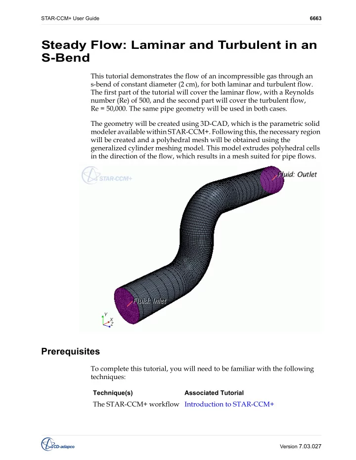
STAR-CCM+ User Guide 6663 Steady Flow: Laminar and Turbulent in an S-Bend This tutorial demonstrates the flow of an incompressible gas through an s-bend of constant diameter (2 cm), for both laminar and turbulent flow. The first part of the
STAR-CCM+ User Guide 6663 Version 7.03.027
STAR-CCM+ User Guide Steady Flow: Laminar and Turbulent in an S-Bend 6664 Version 7.03.027
STAR-CCM+ User Guide Steady Flow: Laminar and Turbulent in an S-Bend 6665 Version 7.03.027
STAR-CCM+ User Guide Steady Flow: Laminar and Turbulent in an S-Bend 6666 Version 7.03.027
STAR-CCM+ User Guide Steady Flow: Laminar and Turbulent in an S-Bend 6667 Version 7.03.027
STAR-CCM+ User Guide Steady Flow: Laminar and Turbulent in an S-Bend 6668 Version 7.03.027
STAR-CCM+ User Guide Steady Flow: Laminar and Turbulent in an S-Bend 6669 Version 7.03.027
STAR-CCM+ User Guide Steady Flow: Laminar and Turbulent in an S-Bend 6670 Version 7.03.027
STAR-CCM+ User Guide Steady Flow: Laminar and Turbulent in an S-Bend 6671 Version 7.03.027
STAR-CCM+ User Guide Steady Flow: Laminar and Turbulent in an S-Bend 6672 Version 7.03.027
STAR-CCM+ User Guide Steady Flow: Laminar and Turbulent in an S-Bend 6673 Version 7.03.027
STAR-CCM+ User Guide Steady Flow: Laminar and Turbulent in an S-Bend 6674 Version 7.03.027
STAR-CCM+ User Guide Steady Flow: Laminar and Turbulent in an S-Bend 6675 Version 7.03.027
STAR-CCM+ User Guide Steady Flow: Laminar and Turbulent in an S-Bend 6676 Version 7.03.027
STAR-CCM+ User Guide Steady Flow: Laminar and Turbulent in an S-Bend 6677 Version 7.03.027
STAR-CCM+ User Guide Steady Flow: Laminar and Turbulent in an S-Bend 6678 Version 7.03.027
STAR-CCM+ User Guide Steady Flow: Laminar and Turbulent in an S-Bend 6679 Version 7.03.027
STAR-CCM+ User Guide Steady Flow: Laminar and Turbulent in an S-Bend 6680 Version 7.03.027
STAR-CCM+ User Guide Steady Flow: Laminar and Turbulent in an S-Bend 6681 Version 7.03.027
STAR-CCM+ User Guide Steady Flow: Laminar and Turbulent in an S-Bend 6682 Version 7.03.027
STAR-CCM+ User Guide Steady Flow: Laminar and Turbulent in an S-Bend 6683 Version 7.03.027
STAR-CCM+ User Guide Steady Flow: Laminar and Turbulent in an S-Bend 6684 Version 7.03.027
STAR-CCM+ User Guide Steady Flow: Laminar and Turbulent in an S-Bend 6685 Version 7.03.027
STAR-CCM+ User Guide Steady Flow: Laminar and Turbulent in an S-Bend 6686 Version 7.03.027
STAR-CCM+ User Guide Steady Flow: Laminar and Turbulent in an S-Bend 6687 Version 7.03.027
STAR-CCM+ User Guide Steady Flow: Laminar and Turbulent in an S-Bend 6688 Version 7.03.027
STAR-CCM+ User Guide Steady Flow: Laminar and Turbulent in an S-Bend 6689 Version 7.03.027
STAR-CCM+ User Guide Steady Flow: Laminar and Turbulent in an S-Bend 6690 Version 7.03.027
STAR-CCM+ User Guide Steady Flow: Laminar and Turbulent in an S-Bend 6691 Version 7.03.027
STAR-CCM+ User Guide Steady Flow: Laminar and Turbulent in an S-Bend 6692 Version 7.03.027
STAR-CCM+ User Guide Steady Flow: Laminar and Turbulent in an S-Bend 6693 Version 7.03.027
STAR-CCM+ User Guide Steady Flow: Laminar and Turbulent in an S-Bend 6694 Version 7.03.027
2
STAR-CCM+ User Guide Steady Flow: Laminar and Turbulent in an S-Bend 6695 Version 7.03.027
STAR-CCM+ User Guide Steady Flow: Laminar and Turbulent in an S-Bend 6696 Version 7.03.027
STAR-CCM+ User Guide Steady Flow: Laminar and Turbulent in an S-Bend 6697 Version 7.03.027