PRESENTATION OF RESULTS FOR SURFACE PLASTIC DEFORMATION BY LAMINAR - - PDF document

presentation of results for surface plastic deformation
SMART_READER_LITE
LIVE PREVIEW

PRESENTATION OF RESULTS FOR SURFACE PLASTIC DEFORMATION BY LAMINAR - - PDF document

54 Presenting the results of plastic deformation of the surface for laminar graphite cast iron PRESENTATION OF RESULTS FOR SURFACE PLASTIC DEFORMATION BY LAMINAR GRAPHITE CAST IRON P. Cosovschi, PhD student Technical University of Moldova


slide-1
SLIDE 1

54 Presenting the results of plastic deformation of the surface for laminar graphite cast iron

PRESENTATION OF RESULTS FOR SURFACE PLASTIC DEFORMATION BY LAMINAR GRAPHITE CAST IRON

  • P. Cosovschi, PhD student

Technical University of Moldova

INTRODUCTION

The process of cold plastic deformation by ball bearing roller aims to achieve active areas of workpieces of better quality surfaces and to increase surface hardness by hardening the superficial layer

  • f material. These attributes give a workpiece a

longer lifetime and greater mechanical properties in the interested area. Earlier was thought to be impossible to use this processing method for cast

  • iron. Analysis of the literature and the experiments

carried out in recent years in the Technical University of Moldova and Technical University of Iasi laboratories and machine workshop of the Chisinau Glass Factory showed promising method

  • f diamond smoothing for laminar graphite cast iron

used in glass industry for molds production.

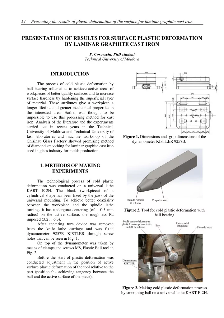
  • 1. METHODS OF MAKING

EXPERIMENTS

The technological process of cold plastic deformation was conducted on a universal lathe KART E-2H. The blank (workpiece) of a cylindrical shape has been fixed by the jaws of the universal mounting. To achieve better coaxiality between the workpiece and the spindle lathe turnings it has undergone centering (of ~ 0.5 mm radius) on the active surface, the roughness Ra imposed (3.2 ... 6.3). After centering turn device was removed from the knife lathe carriage and was fixed dynamometer 9257B KISTLER through screw holes that can be seen in Fig. 1. On top of the dynamometer was taken by means of clamps and screws M8, Plastic Ball tool in

  • Fig. 2.

Before the start of plastic deformation was conducted adjustment in the position of active surface plastic deformation of the tool relative to the part (position 0 - achieving tangency between the ball and the active surface of the piece). Figure 1. Dimensions and grip dimensions of the dynamometer KISTLER 9257B. Figure 2. Tool for cold plastic deformation with ball bearing Figure 3. Making cold plastic deformation process by smoothing ball on a universal lathe KART E-2H.

slide-2
SLIDE 2

Presenting the results of plastic deformation of the surface for laminar graphite cast iron 55

During the application process of plastic deformation, the mandrel drives the workpiece in rotation with constant angular velocity. Tool that make plastic deformation must make two movements: a longitudinal feed axis and a radial feed lathe for carrying out depth of the material layer to be hardened Fig. 3. In the case of cylindrical parts with the active surface is not required to be synchronized to the two

  • movements. The workpieces with complicated

shapes requires a synchronization of the two movements for the perfect tracking with ball of tool for deformation profile parts. During the course of cold plastic deformation process at the contact between the ball and the active surface of the workpiece is developing forces and moments in the three directions. Plastic deformation tool being connected jointly by the dynamometer makes it possible to transfer forces from sensors which are incorporated into this. Therefore they generate electrical signals through cables with connectors are captured by a signal amplifier "Charge amplifier type 5070" which filters and amplifies the signals from the dynamometer. Furthermore these signals are transferred to acquisition board installed in one

  • f the slots of computer-desktop. After processing

the information using the purchase card for each test result by an Excel file with the print screen. It captures during the process of plastic deformation evolution graphics forces in the three directions (file "Notepad" showing the time course of the same forces). For the test of work were preserved for study file for forces in the three directions, torques present no interest. Operating mode parameters are:  the speed of the lathe spindle;  radial feed (depth);  longitudinal feed. Were tested on a blank, multiple operating modes obtained by varying the three parameters was obtained by an optimal working regime (Table 1). Also, to minimize the effort of forming a shell type oil used Omala F. Optimum working regime used in cold plastic deformation process are summarized in Table 1. Were supposed to cold plastic deformation process by roller ball bearing two workpieces. In Fig. 4 is Table 1. Parameters for the optimum working carrying out the plastic deformation. shown one of these parts after the cold plastic deformation b) compared with the turning parts). T Figure 4. Work pieces: a) turning and b) the workpiece after cold plastic deformation by roller with ball bearing. Using a FLIR P660 infrared thermocamera were made of the thermal images of the two parts undergone plastic deformation by cold roller ball (Fig. 5). Figure 5. Images of the thermal regime during the cold plastic deformation process by smoothing with ball bearing. Speed [rev. / Min] 380 Longitudinal feed [mm / rev.] 0.09 Radial feed (depth) [mm] 0.2 ( the radius )

slide-3
SLIDE 3

56 Presenting the results of plastic deformation of the surface for laminar graphite cast iron In the tests conducted on the test bench shown above were acquired data on the forces (of the three directions x, y and z) occurring during the cold plasting polishing with ball bearing. Acquisition dates were selected for several representative samples (samples 6, 7, 9 and 12). a) b) c) d) Figure 6. The graph forces that develop during the smoothing process: a) sample no. 6, b) sample no. 7, c) sample no. 9 and d) sample no. 12. After processing the data was obtained graphs for forces that are developed during processing through the deformation of respective parts according to the three directions Figure 6.

CONCLUSION

  • 1. The process of plastic deformation forces Fy and

Fz can be ignored because their value does not exceed 10% of the results.

  • 2. Fluctuations of contact force Fx are the cause

deformation of the material because it represents the constant repetition strictly connected with machined surface roughness.

  • 3. Numerical results similar in all samples is

evidence that precision experiments is satisfactory.

  • 4. Termocamera shows the lack of heating used in

the process and as a result excludes modifications in material.

Bibliography

  • 1. Balakşcin B. C. Teoria i praktika texnologij

mashinostroeniya: V 2-c kN. – M.: Mashinostroenie, 1982 - 218 s.

  • 2. Balter M. A. Uprochnenie detalej mashin M.:
  • Mashinostroenie. 1978. 184 s.
  • 3. Barabici M. B., Horujenko M. V. Nakatyvanie

czilindricheskix zubceatyx koles.- M.: Mashinostroenie, 1970.- 218 s.

  • 4. Mazuru S., Subotin I., Topala P., Scaticailov

S., Cosovschi P., Stingaci I., Mardari A., Botnari

  • V. Lichid de ungere şi răcire// Brevet de invenţie nr.

s 2010 0123. 2011.

  • 5. Topala P., Mazuru S., Beşliu V., Cosovschi P.

Procedeu de durificare a suprafeţelor metalice // Brevet de invenţie nr. a 2011 0054. 2012. Recommended for publication: 22.102.14.