plastic analysis of plastic analysis of
play

Plastic Analysis of Plastic Analysis of Additional loading applied - PDF document

Plastic Analysis of Plastic Analysis of Additional loading applied to Continuo Continuous Beams us Beams 1 the fully plastic structure would lead to collapse . Increasing the applied load until yielding occurs at some locations yielding


  1. Plastic Analysis of Plastic Analysis of Additional loading applied to Continuo Continuous Beams us Beams 1 the fully plastic structure would lead to collapse . Increasing the applied load until yielding occurs at some locations yielding occurs at some locations Design of structures based on will result in elastic-plastic defor- the plastic or limit state mations that will eventually reach approach is increasingly used a fully plastic condition. and accepted by various codes of practice, particularly for steel Fully plastic condition is construction. Figure 1 shows a defined as one at which a typical stress-strain curve for mild t pical stress strain c r e for mild sufficient number of plastic s fficient n mber of plastic steel and the idealized stress- hinges are formed to transform strain response for performing the structure into a mecha- plastic analysis. nism, i.e., the structure is geometrically unstable . 1 2 1 See pages 142 – 152 in your class notes.
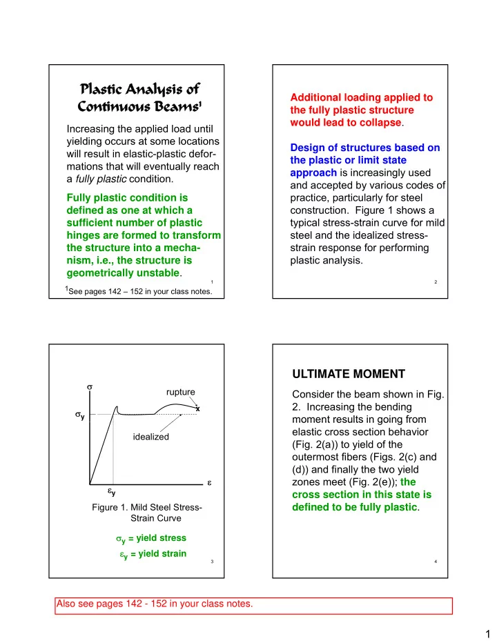
 ULTIMATE MOMENT σ rupture Consider the beam shown in Fig. 2. Increasing the bending x σ y moment results in going from moment results in going from elastic cross section behavior idealized (Fig. 2(a)) to yield of the outermost fibers (Figs. 2(c) and (d)) and finally the two yield ε zones meet (Fig. 2(e)); the ε y cross section in this state is defined to be fully plastic . Figure 1. Mild Steel Stress- Strain Curve σ y = yield stress ε y = yield strain 3 4 Also see pages 142 - 152 in your class notes. 1

  2. The ultimate moment is determined in terms of the yield σ stress . y Since the axial force is zero in this beam case, the neutral axis in the fully plastic condition divides the section into two equal areas , and the resultant tension and compression are σ each equal to A/2, forming a y couple equal to the ultimate Figure. 2. Stress distribution in a sym- plastic moment M p metrical cross section subjected to a bending moment of increasing magni- = σ + 1 M A(y y ) (1) tude: (a) Cross section, (b) Elastic, (c) p y c t 2 Top fibers plastic, (d) Top and bottom fibers plastic, and (e) Fully plastic 5 6 The maximum moment which a c t = distance from neutral axis section can resist without to the extreme tension fiber exceeding the yield stress c c = distance from neutral ( defined as the yield moment axis to the extreme com- M y ) is the smaller of M y ) is the smaller of pression fiber = σ M S (2a) y y t I = moment of inertia = σ M S (2b) y y c α = M p /M y > 1 = shape factor S t = tension section modulus = 1.5 for a rectangular ≡ ( ) ( ) I/c I/c t t section section S c = compression section = 1.7 for a solid circular ≡ modulus ( ) I/c section c = 1.15 – 1.17 for I - or C - section 7 8 2

  3. P PLASTIC BEHAVIOR OF A L SIMPLE BEAM 2 If a load P at the mid-span of a L simple beam (Fig. 3) is (a) Loaded Beam increased until the maximum increased until the maximum M p mid-span moment reaches the fully plastic moment M p , a plastic hinge is formed at this section and collapse will occur under (b) Plastic BMD any further load increase. Since P C this structure is statically deter- this structure is statically deter minate, the collapse load P C can θ θ easily be calculated to give 2 θ Δ (c) Plastic Mechanism = (3) P 4M /L C p Figure 3. Simple Beam 9 10 The collapse load of the beam can be calculated by equating the external and internal work during a virtual movement of the collapse mechanism ( this the collapse mechanism ( this approach is equally applicable to the collapse analysis of sta- tically indeterminate beams ). Equating the external virtual work W e done by the force P C to the internal virtual work W i i done by the moment M p at the Plastic Hinge Along the plastic hinge: Length of the Simple Beam 11 12 3

  4. ULTIMATE STRENGTH OF θ L FIXED-ENDED BEAM = ⇒ = θ W W P M (2 ) e i C p 2 Consider a prismatic fixed-ended ⇒ = beam subjected to a uniform P 4M / L C p load of intensity q (Fig. 4(a)). which is identical to the result hich is identical to the res lt Figure 4(b) shows the moment given in (3). diagram sequence from the yield moment M y 2 q L = σ ≡ I = y M S( ) y y c 12 12M y ⇒ = q y 2 L through the fully plastic condition in the beam. 13 14 q The collapse mechanism is (a) shown in Fig. 4(c) and the col- lapse load is calculated by equa- L ting the external and internal M p virtual works, i.e. θ ⎛ ⎛ ⎞ ⎞ q L L C = θ+ θ+θ (b) ⎜ ⎟ 2 M ( 2 ) p ⎝ ⎠ 2 4 M y M y 16M p ⇒ = q M p M p C 2 L q C Sequence of Plastic Hinge (c) Formation: Δ θ θ 2 θ (1) Fixed-end supports – maxi- mum moment (negative) (2) Mid-span – maximum positive Figure 4. Fixed-Fixed Beam 15 moment 16 4

  5. M p = constant P P ULTIMATE STRENGTH OF (a) L L A 3 D CONTINUOUS BEAMS 2 E F Next consider the three span B C L L L continuous beam shown in Fig. 5 continuous beam shown in Fig. 5 with each span having a plastic P C1 moment capacity of M p . Values (b) of the collapse load correspond- θ θ ing to all possible mechanisms Δ 2 θ 1 are determined; the actual P C2 collapse load is the smallest of ( ) (c) the possible mechanism θ βθ + β Δ collapse loads . 2 Figure 5. (a) Continuous Beam (b) Mechanism 1 (c) Mechanism 2 17 18 For this structure, there are two Figure 5(c) ( Δ 2 = L θ /3): possible collapse mechanisms θ are shown in Figs. 5(b) and (c). ⎛ ⎞ = L θ+θ+β ⎜ ⎟ P M ( ) Using the principle of virtual work C2 p ⎝ ⎠ 3 (W e = W i ) for each mechanism leads to β θ 2L = Δ = L 2 3 3 Figure 5(b) ( Δ 1 = L θ /2): θ ⇒ β = 2 θ ⎛ ⎞ = L θ+ θ+θ θ ⎜ ⎟ P M ( 2 ) θ ⎛ ⎞ 5M L C1 p p ⎝ ⎝ ⎠ ⎠ ∴ = 2 P ⎜ ⎜ ⎟ ⎟ C2 C2 ⎝ ⎝ ⎠ ⎠ 3 2 ⇒ = P 8M / L C1 p ⇒ = P 15M / 2L C2 p 19 20 5

  6. P qL = P The smaller of these two values L (a) is the true collapse load. Thus, q 2 P C = 7.5M p /L and the corres- 2 1 2M p M p ponding bending moment L L diagram is shown below. P C When collapse occurs, the (b) part of the beam between A and C is still in the elastic θ θ Δ 1 range . 2 θ M p (c) q C M < M p θ β β A B C Δ 2 θ + β E D F L 1 -M > -M p -M p Figure 6. (a) Continuous Beam (b) Mechanism 1 Collapse BMD 21 22 (c) Mechanism 2 Mechanism 1: θ P L = Δ = C W P The two span continuous beam e C 1 2 shown in Fig. 6 exhibits some = θ+ θ + θ W 2M 2M (2 ) M unique considerations: i p p p = θ 7M p 1.the plastic moment capacity of 14M span 1-2 is different than the p = ⇒ = W W P (A) e i C plastic moment capacity of L span 2-3; and 2.the location of the positive p M Mechanism 2: h i 2 moment plastic hinge in span Δ Δ 2-3 is unknown. = + − 2 2 W q L q (L L ) e C 1 C 1 2 2 Δ = 2 q L 2 C 23 24 6

  7. = θ+ θ+β The problem with this solution W M M ( ) i p p for q C L is that the length L 1 is θ = Δ = − β L (L L ) unknown . 1 2 1 L L 1 can be obtained by differen- ⇒ β = β 1 θ − tiating both sides of q C L with ti ti b th id f L ith L L L L 1 respect to L 1 and set the result to ⎛ − ⎞ 2L L zero, i.e. ∴ = θ 1 W ⎜ ⎟ M i p − ⎝ ⎠ L L − − 1 d(q L) 2L (L L ) M = C 1 1 ∴ = θ p 1 2 − 2 W q LL dL e C 1 (L ) (L L ) 1 2 1 1 − − 2(2L L )(L 2L )M = − 1 1 W W e i p 2 − 2 (L ) (L L ) ⎛ − ⎞ 1 1 2 2L L ⇒ = 1 (B) = q L ⎜ ⎟ M (C) 0 C p − ⎝ ⎠ L L L 1 1 25 26 Solving (C) for L 1 : Comparing the result in (A) with (E) and for qL = P shows that the 2 2 − + = failure mechanism for this 2L 8LL 4L 0 1 1 beam structure is in span 2-3 . 2 2 ± − 8L (8L) 4(8L ) ⇒ = L 1 1 4 4 = − M < 2M p 2L 2L L 1 = (D) 0.5858L M p Substituting (D) into (B): -M p -M > -2M p 11.66M p = q L C L BMD for Collapse Load q C (E) 27 28 7

  8. Direct Procedure to capacity at end C is M p2 and the Calculate Positive Moment plastic positive moment capacity is M p3 . Plastic Hinge Location for Unsymmetrical Plastic M p1 ≤ M p3 ; M p2 ≤ M p3 p3 ; p1 p2 p3 M Moment Diagram t Di Consider any beam span that is M p3 loaded by a uniform load and the resulting plastic moment diagram is x unsymmetric. Just as shown above the location of the maximum -M 1 M p1 positive moment is unknown. For -M p2 example, assume beam span B – L 1 C is subjected to a uniform load L and the plastic moment capacity at end B is M p1, the plastic moment 29 30 The location of the positive plastic Solving for a and b from (ii) and moment can be determined using (iii): the bending moment equation − + (M M ) p1 p3 M(x) = ax 2 + bx + c = a 2 2 L 1 and appropriate boundary + 2(M M ) conditions. p1 p3 = b L (i) x = 0: M = -M p1 = c 1 (ii) x L 1 : M M p3 (ii) x = L 1 : M = M p3 = aL 1 aL 1 2 + bL 1 + c 2 + bL 1 = M p3 + M p1 ⇒ aL 1 (iii) x = L 1 : dM/dx = 0 = 2aL 1 + b 31 32 8

Download Presentation
Download Policy: The content available on the website is offered to you 'AS IS' for your personal information and use only. It cannot be commercialized, licensed, or distributed on other websites without prior consent from the author. To download a presentation, simply click this link. If you encounter any difficulties during the download process, it's possible that the publisher has removed the file from their server.

Recommend


More recommend