
SLIDE 1
STAR-CCM+ User Guide 6663 Version 7.03.027
Steady Flow: Backward Facing Step This tutorial demonstrates the - - PDF document
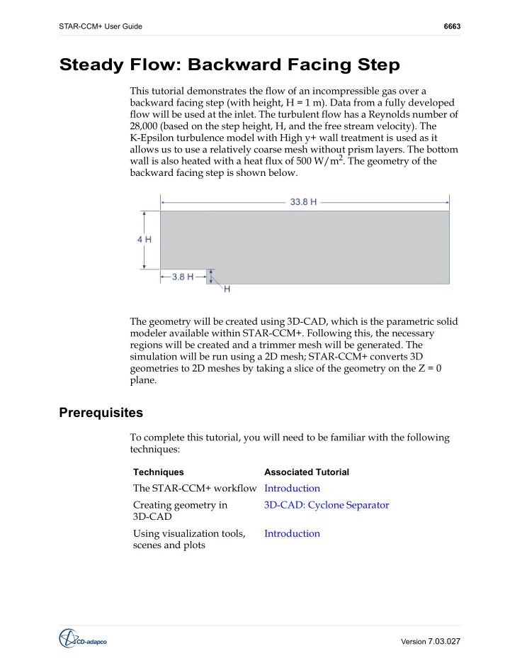
STAR-CCM+ User Guide 6663 Steady Flow: Backward Facing Step This tutorial demonstrates the flow of an incompressible gas over a backward facing step (with height, H = 1 m). Data from a fully developed flow will be used at the inlet. The
STAR-CCM+ User Guide 6663 Version 7.03.027
STAR-CCM+ User Guide Steady Flow: Backward Facing Step 6664 Version 7.03.027
STAR-CCM+ User Guide Steady Flow: Backward Facing Step 6665 Version 7.03.027
STAR-CCM+ User Guide Steady Flow: Backward Facing Step 6666 Version 7.03.027
STAR-CCM+ User Guide Steady Flow: Backward Facing Step 6667 Version 7.03.027
STAR-CCM+ User Guide Steady Flow: Backward Facing Step 6668 Version 7.03.027
STAR-CCM+ User Guide Steady Flow: Backward Facing Step 6669 Version 7.03.027
STAR-CCM+ User Guide Steady Flow: Backward Facing Step 6670 Version 7.03.027
STAR-CCM+ User Guide Steady Flow: Backward Facing Step 6671 Version 7.03.027
STAR-CCM+ User Guide Steady Flow: Backward Facing Step 6672 Version 7.03.027
STAR-CCM+ User Guide Steady Flow: Backward Facing Step 6673 Version 7.03.027
STAR-CCM+ User Guide Steady Flow: Backward Facing Step 6674 Version 7.03.027
STAR-CCM+ User Guide Steady Flow: Backward Facing Step 6675 Version 7.03.027
STAR-CCM+ User Guide Steady Flow: Backward Facing Step 6676 Version 7.03.027
STAR-CCM+ User Guide Steady Flow: Backward Facing Step 6677 Version 7.03.027
STAR-CCM+ User Guide Steady Flow: Backward Facing Step 6678 Version 7.03.027
STAR-CCM+ User Guide Steady Flow: Backward Facing Step 6679 Version 7.03.027
STAR-CCM+ User Guide Steady Flow: Backward Facing Step 6680 Version 7.03.027
STAR-CCM+ User Guide Steady Flow: Backward Facing Step 6681 Version 7.03.027
STAR-CCM+ User Guide Steady Flow: Backward Facing Step 6682 Version 7.03.027
STAR-CCM+ User Guide Steady Flow: Backward Facing Step 6683 Version 7.03.027
STAR-CCM+ User Guide Steady Flow: Backward Facing Step 6684 Version 7.03.027
STAR-CCM+ User Guide Steady Flow: Backward Facing Step 6685 Version 7.03.027
STAR-CCM+ User Guide Steady Flow: Backward Facing Step 6686 Version 7.03.027
STAR-CCM+ User Guide Steady Flow: Backward Facing Step 6687 Version 7.03.027
STAR-CCM+ User Guide Steady Flow: Backward Facing Step 6688 Version 7.03.027
STAR-CCM+ User Guide Steady Flow: Backward Facing Step 6689 Version 7.03.027
STAR-CCM+ User Guide Steady Flow: Backward Facing Step 6690 Version 7.03.027
STAR-CCM+ User Guide Steady Flow: Backward Facing Step 6691 Version 7.03.027
STAR-CCM+ User Guide Steady Flow: Backward Facing Step 6692 Version 7.03.027
STAR-CCM+ User Guide Steady Flow: Backward Facing Step 6693 Version 7.03.027