
SLIDE 1
Status of Advanced Virgo Jo van den Brand, Nikhef and VU University - - PowerPoint PPT Presentation
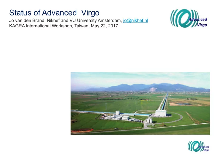
Status of Advanced Virgo Jo van den Brand, Nikhef and VU University Amsterdam, jo@nikhef.nl KAGRA International Workshop, Taiwan, May 22, 2017 Advanced Virgo Virgo is a European collaboration with about 280 members Advanced Virgo (AdV):
Advanced Virgo (AdV): upgrade of the Virgo interferometric detector Participation by scientists from France, Italy, The Netherlands, Poland, Hungary, Spain
2
− APC Paris − ARTEMIS Nice − EGO Cascina − INFN Firenze-Urbino − INFN Genova − INFN Napoli − INFN Perugia − INFN Pisa − INFN Roma La Sapienza − INFN Roma Tor Vergata − INFN Trento-Padova − LAL Orsay – ESPCI Paris − LAPP Annecy − LKB Paris − LMA Lyon − Nikhef Amsterdam − POLGRAW(Poland) − RADBOUD Uni. Nijmegen − RMKI Budapest −
Funding approved in Dec 2009
Goal: be part of the international network
Short-term goal: join the O2 run in 2017 6 European countries
3
4
For 2017
For the period 2018 to 2019
5
Phase 1: Configuration similar to Virgo+ Phase 2: Configuration for best sensitivity Phasing decided to increase the chance to reduce the time gap with LIGO
6
Early configuration Late configuration Virgo+
7
8
Features:
9
Features:
10
11
12
13
AOM shift by 80 MHz
Combine on beam splitter
f1 = 6.270 777 MHz f2 = 56.436 993 MHz f3 = 8.361 036 MHz f4 = 131.686 317 MHz f5 = 22.38 MHz
High speed imaging of HOM Correct aberrations with CO2 lasers
14 bit ADCs at 500 MSPS Xilinks Virtex-7 FPGA
Phase camera Reference beam Sample beam
18
19
20
21
22
23
24
25
System for vertical vibration isolation
creep
13 blades broken (out of about 350) Cause identified: hydrogen embrittlement
Risk mitigation: all the blades showing possible defects in the protective Ni coating have been replaced
Incurred project delay about several months
26
27
Technology already used successfully by Virgo in 2011
28
Technology already used successfully by Virgo in 2011
29
Suspension with steel wires leads to a loss of sensitivity at low frequency
30
All four test masses are suspended with steel wires
31
All four test masses are suspended with steel wires
32
All four test masses are suspended with steel wires
33
Origin of monolithic suspension failures found in fall 2016 Failures could be reproduced in test facility Risk mitigation plan has been defined
34
Venting system
Installation of “fiber guards” as additional safety
35
36
37
38
39
Longest lock stretch about 6 hours BNS range 3-5 Mpc Science mode duty cycle about 84%
40
41
42
43
44
Jul Aug Sep Oct Nov Dec Jan Feb Mar Apr May Jun
Jul
Joint Run Planning Committee
Vent/Commissioning
~75% observing mode
Integration/Commissioning Detector in observing mode for a fraction of the time during Engineering Runs (ERs), EM alerts possible 24/7 observing mode (Observing Run, EM alerts) Detector operational,commissioning mode (small fraction of observing mode time) Detector not producing data (Downtime) O2A
Virgo sensitivity TBC 20-50 Mpc
ER10 O2B O2B O2B
O2B end date to be decided https://dcc.ligo.org/LIGO-L1700023 Decision point
ER11 dates and configuration, duration of the run
Vent/Commissioning
O2A ER10 O2A O2A ER11 ER11 ER11 Aug
Path to join LIGO
(as done in Virgo in 2007) ITF input power to 25 W (now 12.5 W)
hunting
45
46
Maximizing scientific output of AdV
PH PHASE SE 1 1 (2017 2017-18) 18): First run, priority upgrades PH PHASE SE 2 2 (2018 2018-2022) 2022): pushing toward the nominal sensitivity of AdV PH PHASE SE 3 3 (>2022) 2022): Actions to further enhance the AdV sensitivity, exploiting the limits of the present infrastructure and useful in view of a new 3G infrastructure
47
R& R&D Re Requ quired
Run in O2, then… MAIN PRIORITY: Re-install monolithic suspensions NEXT PRIORITIES: Increase of laser power Installation of squeezing Implementation of signal recycling Longer term upgrades to reach the ultimate infrastructure limits (new resources are needed)
48
Quantum noise: Shot noise (X1), error on photon counting Radiation pressure noise (X2): back-action noise caused by fluctuating number of photons hitting the mirrors Uncertainty relation: DX1 DX2 ≥ 1 Squeezing: But…we can reduce the uncertainty in one quadrature increasing it in the other This is done by a SQUEEZER. Already demonstrated on interferometers
49
10
2
10
3
10
−23
10
−22
10
−21
Frequency (Hz) Strain Sensitivity [1 / √ Hz] Typical noise without squeezing Squeezing−enahnced sensitivity
GEO600 LIGO H1
LIGO Scient. Coll., Nature Physics, 2011 L Barsotti, LIGO-G1300420
Virgo squeezing activities: Experiment to realize a Virgo squeezer already funded by CSN2 Focus on an in-vacuum squeezing bench A goal already achieved: skilled team build up AEI Hannover offered their squeezer (best ever realized) to Virgo! Virgo happy to accept the offer:
Work done so far not lost:
squeezing
50
Smaller (25%) compared to GEO-Squeezer
Less components but better performance Fully automated analog control On-board subcomponents:
51
Henning Vahlbruch, February 21, 2017; EGO, Cascina, Italy
Shell has funded the development of sensors suitable for realizing a large network dedicated to NN subtraction A ~1 ME grant has been awarded to the Virgo Polish groups to develop the DAQ for NN subtraction
52
INNOSEIS
53
Step 1: Seismic study to understand soil structure Seismic study Virgo site Characteristics
sensors Techniques
Parameters
Step 3: Model NN and subtraction algorithms '()) = * + , -, / 123
2
Status:
Matlab ElastoDynamic toolbox, KU Leuven
Maria Bader
Step 2: Seismic ground model
parameters
Advanced Virgo integration completed late 2016 Full ITF commissioning started in November 2016
Some improvement possible before the last O2 run
Several upgrades foreseen before the start of O3
54