Synergies and Collaboration between CLIC and ILC on e+/e- Linear - - PowerPoint PPT Presentation

synergies and collaboration between clic and ilc on e e
SMART_READER_LITE
LIVE PREVIEW

Synergies and Collaboration between CLIC and ILC on e+/e- Linear - - PowerPoint PPT Presentation

C L I C C L I C Synergies and Collaboration between CLIC and ILC on e+/e- Linear Collider studies http://clic-study.web.cern.ch/CLIC-Study/ http://www.linearcollider.org/cms/ CLIC @ OXFORD 22-05-08 J .P.Delahaye 1 OUTLINE C L I C C L I C


slide-1
SLIDE 1

C L I C C L I C

CLIC @ OXFORD 22-05-08 J.P.Delahaye 1

Synergies and Collaboration between CLIC and ILC

  • n e+/e- Linear Collider studies

http://clic-study.web.cern.ch/CLIC-Study/ http://www.linearcollider.org/cms/

slide-2
SLIDE 2

C L I C C L I C

CLIC @ OXFORD 22-05-08 J.P.Delahaye 2

OUTLINE

  • Linear Colliders in the HEP world-wide landscape
  • The Compact Linear Collider (CLIC) concept
  • Design and new parameters recently adopted
  • Main challenges and key issues
  • The facilities to address the feasibility issues
  • Plans and schedule
  • Synergies and Collaboration with the ILC
  • Possible UK contribution
  • Conclusion
slide-3
SLIDE 3

C L I C C L I C

CLIC @ OXFORD 22-05-08 J.P.Delahaye 3

World consensus about a Linear Collider as the next HEP facility after LHC

  • 2001: ICFA recommendation of a world-wide

collaboration to construct a high luminosity e+/e- Linear Collider with an energy range up to at least 400 GeV/c

  • 2003: ILC-Technical Review Committee to assess the

technical status of the various designs of Linear Colliders

  • 2004: International Technology Recommendation Panel

selecting the Super-Conducting technology for an International Linear Collider (ILC) Linear Collider in the TeV energy range

  • 2004: CERN council support for R&D addressing the

feasibility of the CLIC technology to possibly extend Linear Colliders into the Multi-TeV energy range.

slide-4
SLIDE 4

C L I C C L I C

CLIC @ OXFORD 22-05-08 J.P.Delahaye 4

CERN Council Strategy Group (Lisbon July 2006)

slide-5
SLIDE 5

C L I C C L I C

CLIC @ OXFORD 22-05-08 J.P.Delahaye 5

  • Ecm adjustable from 200 – 500 GeV
  • Luminosity

∫Ldt = 500 fb-1 in 4 years

  • Ability to scan between 200 and 500 GeV
  • Energy stability and precision below 0.1%
  • Electron polarization of at least 80%
  • The machine must be upgradeable to 1 TeV
slide-6
SLIDE 6

C L I C C L I C

CLIC @ OXFORD 22-05-08 J.P.Delahaye 6

The ILC Plan and Schedule The ILC Plan and Schedule

2005 2006 2007 2008 2009 2010

Global Design Effort Project

Baseline configuration Reference Design ILC R&D Program Technical Design Expression of Interest to Host International Mgmt

LHC Physics

CLIC (B.Barish/CERN/SPC 050913)

slide-7
SLIDE 7

C L I C C L I C

CLIC @ OXFORD 22-05-08 J.P.Delahaye 7

Site independent feasibility study aiming at the development of a realistic technology to extend e-/e+ linear colliders into the Multi- TeV energy range:

ECM energy range complementary to LHC =>ECM = 0.5- 3 TeV L > few 1034 cm-2 with acceptable background ⇒ ECM and L to be reviewed when LHC physics results avail. Affordable cost and power consumption

Physics motivation: http://clicphysics.web.cern.ch/CLICphysics/

"Physics at the CLIC Multi-TeV Linear Collider: by the CLIC Physics Working Group:CERN 2004-5

Present goal:

Demonstrate all key feasibility issues and document in a Conceptual Design Report by 2010 and possibly Technical Design Report by 2015

CLIC Advisory CommitteE (ACE):

L.Evans/CERN, M.Huening/DESY, A.Mosnier/CEA, P.Raimondi/INFN, V.Shiltsev/FNAL, T.Shintake/RIKEN, T.Raubenheimer/SLAC (Chairman), N.Toge/KEK

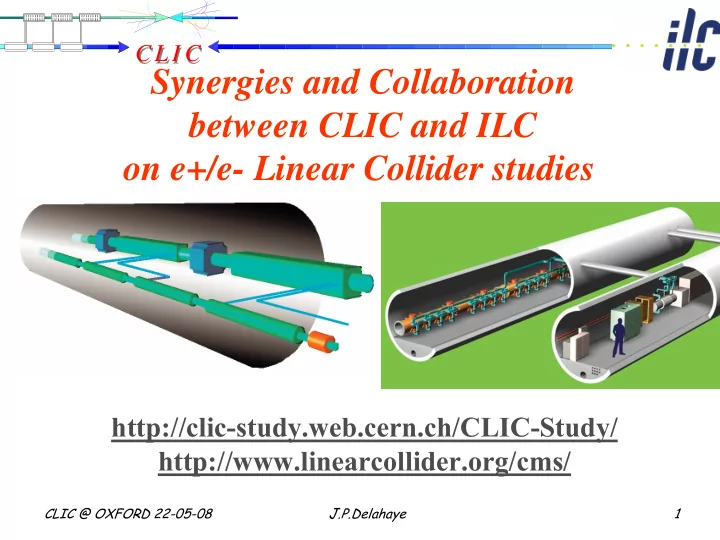
THE COMPACT LINEAR COLLIDER (CLIC) STUDY

http://clic-study.web.cern.ch/CLIC-Study/

slide-8
SLIDE 8

C L I C C L I C

CLIC @ OXFORD 22-05-08 J.P.Delahaye 8

CLIC – basic features

  • “Compact” collider – total length < 50 km at 3 TeV
  • Normal conducting acceleration structures at high

frequency

  • Novel Two-Beam Acceleration Scheme
  • Cost effective, reliable, efficient
  • Simple tunnel, no active elements
  • Modular, easy energy upgrade in stages

CLIC TUNNEL CROSS-SECTION

4.5 m diameter

QUAD QUAD POWER EXTRACTION STRUCTURE BPM ACCELERATING STRUCTURES

Drive beam - 95 A, 240 ns from 2.4 GeV to 240 MeV Main beam – 1 A, 156 ns from 9 GeV to 1.5 TeV 100 MV/m

12 GHz – 64 MW

  • High acceleration gradient: > 100 MV/m
slide-9
SLIDE 9

C L I C C L I C

CLIC @ OXFORD 22-05-08 J.P.Delahaye 9

e+ injector, 2.4 GeV e- injector 2.4 GeV

CLIC overall layout 3 TeV

e

+

main linac e

  • main linac , 12 GHz, 100 MV/m, 21 km

BC2 BC2 BC1 e+ DR 365m e- DR 365m decelerator, 24 sectors of 868 m

IP1

BDS 2.75 km BDS 2.75 km booster linac, 9 GeV, 2 GHz

48 km

drive beam accelerator 2.37 GeV, 1.0 GHz combiner rings

Circumferences delay loop 80.3 m CR1 160.6 m CR2 481.8 m

CR1 CR2 delay loop 326 klystrons 33 MW, 139 μs 1 km CR2 delay loop drive beam accelerator 2.37 GeV, 1.0 GHz 326 klystrons 33 MW, 139 μs 1 km CR1 TA

R=120m

TA

R=120m 245m 245m

Drive Beam Generation Complex Main Beam Generation Complex

slide-10
SLIDE 10

C L I C C L I C

CLIC @ OXFORD 22-05-08 J.P.Delahaye 10

Strategy to address key issues

  • Key issues common to all Linear Collider studies

independently of the chosen technology in close collaboration with the International Linear Collider (ILC) study:

  • On Accelerator Test Facility (ATF1&ATF2@KEK)
  • With European Laboratories in the frame of the Coordinated

Accelerator Research in Europe (CARE) and of a “Design Study” (EUROTeV) funded by EU Framework Programmes (FP6 presently and FP7 Integrated Activity in the future)

  • Key issues specific to CLIC technology:
  • Focus of the CLIC study
  • All R1 (feasibility) and R2 (design finalisation) key issues

addressed in test facilities: CTF1,2,3@CERN

slide-11
SLIDE 11

C L I C C L I C

CLIC @ OXFORD 22-05-08 J.P.Delahaye 11

Close CLIC & ILC Collaboration

  • CLIC study members participating to ILC GDE
  • Major partners in specific studies and ILC Reference Design Report
  • ILC@CERN Site Specific Cost Study (CERN = European sample site)
  • Key ILC experts in CLIC Advisory Committee
  • Fruitful collaboration on R&D of generic Linear Colliders (CLIC&ILC) key

issues

  • Participation in EUROTeV design study & CARE project
  • R&D on Beam diagnostics, Beam Delivery System (BDS), Beam dynamics
  • Tests with beam in CTF3 Test facility
  • Common participation to R&D on generation of Low Emittances generation @

ATF1/KEK and Strong Beam Focusing to nanometers sizes @ATF2/KEK

  • Future common study of subjects with strong synergy between CLIC & ILC
  • FP7 EU supported in Coordinated Accelerator R&D (EUCARD) with a CLIC/ILC

work package (NC Linacs)

  • Launching common CLIC/ILC studies with ILC Project Managers (Feb08 @ CERN)

following constructive visit of B.Barish (Nov 07):

– Civil engineering & conventional facilities

– Beam delivery System and Machine –Detector Interface – Physics & Detectors – Cost & Schedule

– ….

slide-12
SLIDE 12

C L I C C L I C

CLIC @ OXFORD 22-05-08 J.P.Delahaye 12

* India participating through a special agreement with CERN for the development of novel accelerator technologies

20 members representing 25 institutes involv. 17 funding agencies from 14 countries

  • Collab. Board: Chairperson: M.Calvetti/INFN; Spokesperson: G.Geschonke/CERN

MoU with addenda describing specific contribution (& resources)

CLIC/CTF3 Multi-Lateral Collaboration of Volunteer Institutes

Organized as a Physics Detector Collaboration

slide-13
SLIDE 13

C L I C C L I C

CLIC @ OXFORD 22-05-08 J.P.Delahaye 13

CLIC/CTF3 collaboration observers

Present collaboration with RAL on Laser development for PHIN in EU FP6 CARE

MoUs being finalized Discussion with possible future collaboration partners: Visiting Scientist: MoU being finalized

slide-14
SLIDE 14

C L I C C L I C

CLIC @ OXFORD 22-05-08 J.P.Delahaye 14

Finnish Industry (Finland) Gazi Universities (Turkey) Helsinki Institute of Physics (Finland) IAP (Russia) Instituto de Fisica Corpuscular (Spain) INFN / LNF (Italy)

  • J. Addams Institute (UK)

Oslo University (Norway) PSI (Switzerland) North-West. Univ. Illinois (USA)

  • Polytech. University of Catalonia (Spain)

RAL (UK) SLAC (USA) Svedberg Laboratory (Sweden) Uppsala University (Sweden) Ankara University (Turkey) Berlin Tech. Univ. (Germany) BINP (Russia) CERN CIEMAT (Spain) DAPNIA/Saclay (France) RRCAT-Indore (India) JASRI (Japan) Jefferson Lab (USA) JINR (Russia) KEK (Japan) LAL/Orsay (France) LAPP/ESIA (France) LLBL/LBL (USA) NCP (Pakistan)

World-wide CLIC&CTF3 Collaboration

slide-15
SLIDE 15

C L I C C L I C

CLIC @ OXFORD 22-05-08 J.P.Delahaye 15

DRIVE BEAM LINAC CLEX

CLIC Experimental Area

DELAY LOOP COMBINER RING

CTF3 – Layout

10 m

4 A – 1.2 μs 150 Mev 30 A – 140 ns 150 Mev

Addressing all major CLIC technology key issues in CLIC Test Facility (CTF3)

First Accelerator R&D recognized as CERN Physics Experiment (Grey Book)

slide-16
SLIDE 16

C L I C C L I C

CLIC @ OXFORD 22-05-08 J.P.Delahaye 16

2005 2004

CLEX CR TL1 DL TL2 Jan 2007 Beam up to here

Demonstrate Drive Beam generation (fully loaded acceleration, beam intensity and bunch frequency multiplication x8) Demonstrate RF Power Production and test Power Structures (PETS) Demonstrate Two Beam Acceleration and test Accelerating Structures Demonstrate Drive Beam generation (fully loaded acceleration, beam intensity and bunch frequency multiplication x8) Demonstrate RF Power Production and test Power Structures (PETS) Demonstrate Two Beam Acceleration and test Accelerating Structures

Cleaning Chicane First module INJECTOR

CTF3 Continuous 0peration (10months/year)

HW & Beam Commisioning and RF power production for structure tests

slide-17
SLIDE 17

C L I C C L I C

CLIC @ OXFORD 22-05-08 J.P.Delahaye 17

CERN LAL SLAC IAP INFN-LNF CIEMAT BINP LURE CERN NWU LAPP Uppsala RRCAT TSL CERN CEA-DAPNIA CERN LAL Uppsala CERN CIEMAT UPC IFIC CERN

CTF3 – Collaborations

CERN NWU PSI Uppsala INFN-LNF CERN INFN-LNF CERN

Work Package repartition

slide-18
SLIDE 18

C L I C C L I C

CLIC @ OXFORD 22-05-08 J.P.Delahaye 18

CTF3 – R&D Issues - where

fully loaded acceleration recombination x 2 phase-coding bunch length control recombination x 4 bunch compression PETS

  • n-off

two-beam acceleration structures 12 GHz structures 30 GHz deceleration stability

TRC Issues addressed When? R1.1 – structures 2006-10 R1.2 – DB generation 2006-08 R1.3 – PETS on-off 2009-10 R 2.1– structure materials 2006-10 R 2.2 – DB decelerator 2009-10 R 2.3 – CLIC sub-unit 2008-10

CLIC Technology Feasibility Key Issues

slide-19
SLIDE 19

C L I C C L I C

CLIC @ OXFORD 22-05-08 J.P.Delahaye 19

MKS0 3 MKS07 MKS06 MKS05 Spectrometer 10 Spectrometer 4

RF pulse at structure output RF pulse at structure input analog signal 1.5 µs beam pulse

Drive beam generation with full beam-loading acceleration in CTF3 linac

  • Measured RF-to-beam

efficiency 95.3%

  • Theory 96%

(~ 4 % ohmic losses)

SiC load Damping slot

Dipole modes suppressed by slotted iris damping (first dipole’s Q factor < 20) and HOM frequency detuning

slide-20
SLIDE 20

C L I C C L I C

CLIC @ OXFORD 22-05-08 J.P.Delahaye 20

Beam intensity and RF frequency multiplication (factor 2) in CTF3 Delay Loop

500 1000 1500 2000 2 4 6 t [ns] I [A]

slide-21
SLIDE 21

C L I C C L I C

CLIC @ OXFORD 22-05-08 J.P.Delahaye 21

First circulating beam (May `07)

Beam commissioning of the Combiner ring

Intensity and Frequency multiplication by factor 4 (3 to 12 GHz)

2.6 A 8.5 A

slide-22
SLIDE 22

C L I C C L I C

CLIC @ OXFORD 22-05-08 J.P.Delahaye 22

CLIC Experimental Area (CLEX)

Construction on schedule Equipment installation from May 2007, Beam foreseen from March 2008

Jan 2007 June 2006

CERN contributionions to ITB Floor space Technical infrastructure Magnet and Vacuum power supplies Control system infrastructure Cabling

Sept o7

  • Test beam line (TBL) to study RF power production (2.5 TW at 12

GHz) and drive beam decelerator dynamics, stability & losses

  • Two Beam Test Stand to study probe beam acceleration with high

fields at high frequency and the feasibility of Two Beam modules

slide-23
SLIDE 23

C L I C C L I C

CLIC @ OXFORD 22-05-08 J.P.Delahaye 23

RF Power production in CTF3

CTF3 linac

Power extraction & transfer structure (PETS)

High-gradient test stand Low-loss transfer line

  • Produced power at 30 GHz up to about 100 MW – long pulses (up to

300 ns) available for the first time

  • Structure tests started in 2005 - 8 structures tested until now
slide-24
SLIDE 24

C L I C C L I C

CLIC @ OXFORD 22-05-08 J.P.Delahaye 24

PETS parameters:

Aperture = 23 mm Period = 6.253 mm (900/cell) Iris thickness = 2 mm R/Q = 2258 Ω V group= 0.453 Q = 7200 P/C = 13.4 E surf. (135 MW)= 56 MV/m H surf. (135 MW) = 0.08 MA/m (∆T max (240 ns, Cu) = 1.8 C0)

To reduce the surface field concentration in the presence of the damping slot, the special profiling of the iris was adopted.

E-field H-field

In its final configuration, PETS comprises eight octants separated by the damping slots. Each of the slots is equipped with HOM damping loads. This arrangement follows the need to provide strong damping of the transverse modes.

CLIC Power Extraction and Transfer Structure (PETS)

  • I. Syratchev
slide-25
SLIDE 25

C L I C C L I C

CLIC @ OXFORD 22-05-08 J.P.Delahaye 25

Testing Accelerating Structures

slide-26
SLIDE 26

C L I C C L I C

CLIC @ OXFORD 22-05-08 J.P.Delahaye 26

CTF3 High-Power test results @ 30 GHz

Pulse Length Gradient

CTF II experiment CLIC goal

E ~ T 1/4 E ~ T 1/6

Reached nominal CLIC values : 150 MV/m - 70 ns

Breakdown Rate not compatible with LC

  • peration
slide-27
SLIDE 27

C L I C C L I C

CLIC @ OXFORD 22-05-08 J.P.Delahaye 27

  • Acceptable Breakdown Rate in linear collider operation not higher than 10-6
  • Reduction of accelerating field by about 30 MV/m for low BR with Cu

Cu Mo

CTF3 High-Power tests various materials results @ 30 GHz

J.A. Rodriguez et al. FROBC01

CLIC

  • perational

goal

slide-28
SLIDE 28

C L I C C L I C

CLIC @ OXFORD 22-05-08 J.P.Delahaye 28

CTF3 - SLAC High-Power test results @ 30 & 11.4 GHz

  • Structures with scaled geometries at different frequencies have same performance

Scaling introduced in a parametric model (taking into account RF structure & beam dynamics constraint), used to study optimum cost & efficiency

30 GHz 11.4 GHz

slide-29
SLIDE 29

C L I C C L I C

CLIC @ OXFORD 22-05-08 J.P.Delahaye 29

CLIC overall optimisation model

Beam dynamics constraints:

Beam quality preservation during acceleration in main linac with high wake fields environment: (conditions similar to NLC) Beam focusing in Beam Delivery System and collison in detector in high beamstrahlung regime

Accelerating structure limitations:

rf breakdown and pulsed surface heating (rf) constraints:

Performance or figure of merit Luminosity per linac input power:

∫Ldt/∫Pdt ~ Lb×/Nη

Deduce CLIC parameters and performance: > 200 millions structures

Cost estimation of the

  • verall complex at 3 TeV

(invest. & exploit. 10 years)

Optimising

slide-30
SLIDE 30

C L I C C L I C

CLIC @ OXFORD 22-05-08 J.P.Delahaye 30

Two Beam Module

20760 modules 71460 power production structures PETS (drive beam) 143010 accelerating structures (main beam)

slide-31
SLIDE 31

C L I C C L I C

CLIC @ OXFORD 22-05-08 J.P.Delahaye 31

CLIC Standard Two Beam Module

slide-32
SLIDE 32

C L I C C L I C

CLIC @ OXFORD 22-05-08 J.P.Delahaye 32

Single CLIC tunnel with alcoves for drive beam return loops and dumps

slide-33
SLIDE 33

C L I C C L I C

CLIC @ OXFORD 22-05-08 J.P.Delahaye 33

Longitudinal section of a laser straight Linear Collider on CERN site– IP under CERN Prevessin site Phase 1: 1 TEV extension 19.5 km Phase 2: 3 TeV extension 48.5 km

Detectors and Interaction Point CERN site Prevessin

slide-34
SLIDE 34

C L I C C L I C

CLIC @ OXFORD 22-05-08 J.P.Delahaye 34

CLIC performances (FoM) and cost (relative) as a function of the accelerating gradient

  • Performances increasing with lower accelerating gradient

(mainly due to higher efficiency)

  • Flat cost variation in 100 to 130 MV/m with a minimum

around 120 MV/m

Ecms = 3 TeV L(1%) = 2.0 1034 cm-2s-1

Previous Previous New New Optimum

Figure of Merit Performance Cost

slide-35
SLIDE 35

C L I C C L I C

CLIC @ OXFORD 22-05-08 J.P.Delahaye 35

CLIC performances (FoM) and cost optimisation as function of RF frequency

Ecms = 3 TeV L(1%) = 2.0 1034 cm-2s-1

  • Maximum Performance around 14 GHz
  • Flat cost variation in 12 to 16 GHz frequency range with a

minimum around 14 GHz

New New Previous Previous Optimum Optimum

Performance Cost

slide-36
SLIDE 36

C L I C C L I C

CLIC @ OXFORD 22-05-08 J.P.Delahaye 36

The beauty of 12 GHz

  • Close to maximum Performance and minimum Cost (14 GHz)
  • Very close to the NLC and JLC frequency: 11.4 GHz
  • Building up on wide expertise and long-term R&D made during many

years on warm structures, RF power sources, beam dynamics at SLAC and KEK

  • Take advantage of low(er than 30 GHz) frequency for easier fabrication

(tolerances, vacuum), relaxed requirements (alignment, timing, etc…),

  • RF power generation and frequency multiplication in CLIC TBA RF

Power Source

  • Possibly drive beam linac at 1.3 GHz (with possible synergy with ILC

MBK developments) and multiplication by 8 (2*4) instead 36

  • High gradients achievable with short RF pulse provided by TBA RF

power source

  • Easy adaptation of CTF3 (multiplication factor by 8 instead of 10)
  • Stand alone power sources available:
  • Makes the best use of developments and equipments at SLAC and KEK
slide-37
SLIDE 37

C L I C C L I C

CLIC @ OXFORD 22-05-08 J.P.Delahaye 37

Collaboration with SLAC

slide-38
SLIDE 38

C L I C C L I C

CLIC @ OXFORD 22-05-08 J.P.Delahaye 38

Collaboration with KEK

slide-39
SLIDE 39

C L I C C L I C

CLIC @ OXFORD 22-05-08 J.P.Delahaye 39

Main Linac RF frequency Main Linac RF frequency 30 GHz 30 GHz ⇒ ⇒ 12 GHz 12 GHz Accelerating field Accelerating field 150 MV/m 150 MV/m ⇒ ⇒ 100 MV/m 100 MV/m Overall length @ E Overall length @ ECMS

CMS= 3 TeV

= 3 TeV 33.6 km 33.6 km ⇒ ⇒ 48.2 km 48.2 km

  • Substantial cost savings and performance improvements for 12

Substantial cost savings and performance improvements for 12 GHz / 100 MV/m GHz / 100 MV/m indicated by parametric model (flat optimum in parameter range) indicated by parametric model (flat optimum in parameter range)

  • Promising results already achieved with structures in test c

Promising results already achieved with structures in test conditions close to LC

  • nditions close to LC

requirements (low breakdown rate) but still to be demonstrated w requirements (low breakdown rate) but still to be demonstrated with long RF pulses ith long RF pulses and fully equipped structures with HOM damping. and fully equipped structures with HOM damping.

  • Realistic feasibility demonstration by 2010

Realistic feasibility demonstration by 2010

New CLIC Parameters (December 2006)

slide-40
SLIDE 40

C L I C C L I C

CLIC @ OXFORD 22-05-08 J.P.Delahaye 40

Latest data

CLIC target

Improvement by RF conditionning (under progress)

A shining example of fruitful collaboration

T18_VG2.4_disk: Designed at CERN, Built at KEK, RF Tested at SLAC

slide-41
SLIDE 41

C L I C C L I C

CLIC @ OXFORD 22-05-08 J.P.Delahaye 41

Accelerating Structure Performances

Accelerating Structure Performances

T53vg3 11.4 GHz 2007 C40vg8 30 GHz 2006 NLC design 11.4 GHz CLIC design 12 GHz SLC operation 3 GHz ILC design SC 1.3 GHz T18vg24 11.4 GHz 2008 0.0 5.0 10.0 15.0 20.0 25.0 30.0 35.0 40.0 45.0 50.0 20 40 60 80 100 120 Loaded & Average Accelerating Field (MV/m) RF to Beam efficiency (%)

slide-42
SLIDE 42

C L I C C L I C

CLIC @ OXFORD 22-05-08 J.P.Delahaye 42

12 GHz Structure Tests Flow Chart

CLICvg1 geometry OK 2008 2007 CLICvg1 geometry not OK Disks OK Quads OK +Damp 2009 CLIC prototype disks damped CLIC prototype TD28 like CLIC prototype quads damped Go towards more extreme structures 2010 Input from break down R&D TD18_vg2.4_quad T28_vg2.9 T18_vg2.4_disk TD28_vg2.9 (T18_vg2.4_quad) TD18_vg2.4_disk

?

Damping Not OK

slide-43
SLIDE 43

C L I C C L I C

CLIC @ OXFORD 22-05-08 J.P.Delahaye 43

Apr-Jun Jul-Sep Oct-Dec CTF3/CERN 30 GHz NLCTA/SLAC Station 1 11.4 GHz

C30_vg2.6

XTF/KEK 11.4 GHz Jan-Mar Current structure testing program

C30_vg8.2 C30_vg2_TM02

NLCTA/SLAC Station 2 11.4 GHz 2008

C10vg2.9 [2x] C10vg0.6 [2x] C10vg2.4_ thick [2x] T18_vg2.4_ disk TD18_vg2.4 T18_vg2.4_ disk [2] TD18_vg2.4 _quad [2] PETS 11.4 GHz HDS11_vg2 TD18_vg2.4 _quad T28_vg2.9 C10_vg1.5 TD18_vg2.4 [2] C10vg1.5 [2x]

CLEX/CTF3 12GHz

T18_vg2.4_disk PETS 12 GHz

slide-44
SLIDE 44

C L I C C L I C

CLIC @ OXFORD 22-05-08 J.P.Delahaye 44

Center-of-mass energy 3 TeV Peak Luminosity 7·1034 cm-2 s-1 Peak luminosity (in 1% of energy) 2·1034 cm-2 s-1 Repetition rate 50 Hz Loaded accelerating gradient 100 MV/m Main linac RF frequency 12 GHz Overall two-linac length 41.7 km Bunch charge 4·109 Beam pulse length 200 ns Average current in pulse 1 A Hor./vert. normalized emittance 660 / 20 nm rad Hor./vert. IP beam size bef. pinch 53 / ~1 nm Total site length 48.25 km Total power consumption 322 MW

Provisional values Provisional values

New CLIC main parameters

slide-45
SLIDE 45

C L I C C L I C

CLIC @ OXFORD 22-05-08 J.P.Delahaye 45

Main CLIC/ILC parameters @ various energies

https://clic-meeting.web.cern.ch/clic-meeting/ComparisonTable_RC_12oct07.html

19.5 12.0 7.0 14.0 2

42 14 7 48 19.5 12 Horizontal beam size at IP before pinch Vertical beam size at IP before pinch 40 1 142 2 640 5.7

slide-46
SLIDE 46

C L I C C L I C

CLIC @ OXFORD 22-05-08 J.P.Delahaye 46

Beam emittances at Damping Rings

30

SLC ATF Design

CLIC TeV 3 CLIC GeV 500 ILC GeV 500

ATF achieved 0.001 0.010 0.100 1.000 10.000 0.1 1 10 100

Horizontal Emittance (μrad-m) Vertical Emittance (μrad-m)

slide-47
SLIDE 47

C L I C C L I C

CLIC @ OXFORD 22-05-08 J.P.Delahaye 47

Beam sizes at Collisions

R.M.S. Beam Sizes at Collision in Linear Colliders

ILC 500 CLIC 500 CLIC 3000 FFTB SLC ATF2

0.1 1 10 100 1000 10 100 1000

Horizontal Beam Size (nm) Vertical Beam Size (nm)

slide-48
SLIDE 48

C L I C C L I C

CLIC @ OXFORD 22-05-08 J.P.Delahaye 48

Performances of Lepton Colliders

LEP SLC ILC CLIC

1.E+30 1.E+31 1.E+32 1.E+33 1.E+34 1.E+35 1 2 3 4 5

Energy (TeV) Luminosity (cm-2 sec-1)

slide-49
SLIDE 49

C L I C C L I C

CLIC @ OXFORD 22-05-08 J.P.Delahaye 49

CLIC Work program till 2010

  • Work programme and resources (2007-2015)

http://clic-meeting.web.cern.ch/clic-meeting/2007/CLIC_ACE/201006_CLIC_LTP_2006_15.pdf

  • Demonstrate feasibility of CLIC technology in CTF3
  • Design of a linear Collider based on CLIC technology

http://clic-study.web.cern.ch/CLIC-Study/Design.htm

  • Estimation of its cost in the CERN area and comparison

with ILC

  • CLIC Physics study and detector development:

http://clic-meeting.web.cern.ch/clic-meeting/CLIC_Phy_Study_Website/default.html

  • Preparation of a Conceptual Design Report to be

published in 2010

slide-50
SLIDE 50

C L I C C L I C

CLIC @ OXFORD 22-05-08 J.P.Delahaye 50

CERN, 16-18 October 2007 CERN, 16-18 October 2007

CLIC Workshop 07 CLIC Workshop 07

CLI C'0 7 provides a forum to review all aspects related to the Accelerator, Detector and Particle Physics of a Multi-TeV Linear Collider based on the CLIC technology. I t is open to any interested Accelerator and Physics expert already part or not of the CLIC/ CTF3 collaboration. The workshop will address in particular:

  • Present status and future plans of the CLIC study
  • CLIC physics case and detector issues
  • The Test Facility CTF3 used to address major CLIC

technology issues

  • The ongoing CLIC R&D, future plans (including FP7

proposals) and open issues

  • The CLIC related collaborative efforts

The CLI C w orkshop w ill be held at CERN in the Main Auditorium , Main building, 1 st Floor Local Organising Com m ittee

  • H.H. Braun (Chair)
  • R. Corsini
  • J-P. Delahaye
  • J. Ellis
  • S. Escaffre
  • G. Geschonke
  • A. de Roeck
  • W.D. Schlatter
  • D. Schulte
  • W. Wuensch

Program Advisory Com m ittee

  • M. Besançon
  • G. Blair
  • M. Calvetti
  • S. Chattopadhyay
  • T. Ekelof
  • A. Faus-Golfe
  • L. Garcia
  • T. Higo
  • H. Hoorani
  • Y. Karyotakis
  • E. Levitchev
  • K. Osterberg
  • M. Poelker
  • L. Rivkin
  • V.C. Sahni
  • G.D. Shirkov
  • S. Tantawi
  • M. Velasco
  • G. Wormser

http://indico.cern.ch/conferenceOtherViews.py?view=standard&confId=17 870

slide-51
SLIDE 51

C L I C C L I C

CLIC @ OXFORD 22-05-08 J.P.Delahaye 51

CLIC 07 participation

200 (registered) from 49 Inst. of 19 countries

  • China: Tsinghua University
  • Finland: Helsinski Univ.- HIP
  • France: CNRS/IN2P3/LAL-LAPP

LPNHE-LPSC, THALES, CEA DAPNIA

  • Germany: DESY-ANKA/FZK
  • Greece: Athens NTU-IASA-

PATRAS

  • India: BARC-RRCAT
  • Iran: IPM
  • Italy: INFN/LNF-Napoly Fed.II
  • Japan: KEK
  • Norway: NTNU
  • Pakistan: NCP
  • Russia: IAP—BINP-JINR
  • Spain: CIEMAT-IFIC-UPC
  • Sweden: Uppsala Univ.
  • Switzerland: CERN-ETHZ-

IPP-PSI

  • Turkey: Ankara U-Dumlupinar U

TOBB Univ Eco&Tech

  • UK: COCKROFT-J.ADAMS-

Lancaster Univ-Oxford- RHUL

  • Ukraine: IAP-NAS
  • USA: LBNL-Northwestern U.-

TJNAF-OHMEGA- Oklahoma Univ-SLAC

slide-52
SLIDE 52

C L I C C L I C

CLIC @ OXFORD 22-05-08 J.P.Delahaye 52

CLIC-ILC Collaboration

  • Following visit of Barry @ CERN (Nov 07)

http://www.linearcollider.org/newsline/archive/2007/20071213.html

Independently of US/UK financial crisis, but even more desirable now

  • CLIC-ILC Collaboration meeting #1 (Feb 08)

http://indico.cern.ch/conferenceDisplay.py?confId=27435

  • GDE/ACFA Meeting at Sendai/Japan (March 08)

http://www.awa.tohoku.ac.jp/TILC08/

  • CLIC-ILC Collaboration meeting #2 (May 08)

http://indico.cern.ch/conferenceDisplay.py?confId=32263

slide-53
SLIDE 53

C L I C C L I C

CLIC @ OXFORD 22-05-08 J.P.Delahaye 53

  • The LHC is going to open a new energy frontier and we all

anticipate the discoveries

  • A complementary lepton collider will almost certainly be

strongly motivated by those discoveries.

  • Different approaches: ILC, CLIC; Muon Collider
  • Issues include technological hurdles; parameters (e.g.

energy); cost; site; timescales

  • The choice should be determined by the science!
  • Common goal! We need to optimize the developments, so a

lepton collider can become a reality.

CLIC-ILC Collaboration

why collaborate?

(B.Barish on May 13, 2008 @ CERN )

slide-54
SLIDE 54

C L I C C L I C

CLIC @ OXFORD 22-05-08 J.P.Delahaye 54

(My) motivations for CLIC/ILC collaboration

  • Lack of resources: (both CLIC and ILC)
  • Join resources where useful and avoid duplication
  • Foster ideas and favor exchanges
  • Beneficial to both
  • Aiming (as much as possible) on common system designs
  • similar energy; Ex: BDS, MDI, Detector, Cost….
  • Identify necessary differences due to technology and/or energy
  • Avoid negative image of conflicting teams
  • Devastating for HEP
  • Minimize contradicting presentations in 2010-12 (?):
  • Develop common knowledge of both designs and technologies on status,

advantages, issues and prospects for the best use of future HEP

  • Common preparation of the (unavoidable) evaluation of technology
  • Avoid (another) evaluation by external (wise?) body. Better done by this

community with technical expertise

  • Even if ILC technology more mature, timescale not so ≠ :
  • Technical Design in 2010-2012 for ILC and 2014 for CLIC
slide-55
SLIDE 55

C L I C C L I C

CLIC @ OXFORD 22-05-08 J.P.Delahaye 55

LHC, ILC & CLIC Schedules

2007 2009 2010 2011 2012 2013 2014 2015 2016 2017 2018 2019 2020 2021 2022 2023 2024

LHC

LHC Operation + LHC upgrade SLHC Operation ILC CLIC R&D, Conceptual Design & Cost Estimation Commissioning & Operation Technical design & industrialisation Construction (first stage) Project approval & final cost 2008

slide-56
SLIDE 56

C L I C C L I C

CLIC @ OXFORD 22-05-08 J.P.Delahaye 56

DG to CERN staff Jan 08

slide-57
SLIDE 57

C L I C C L I C

CLIC @ OXFORD 22-05-08 J.P.Delahaye 57

ILC Layout

slide-58
SLIDE 58

C L I C C L I C

CLIC @ OXFORD 22-05-08 J.P.Delahaye 58

CLIC ILC working groups

  • Co-conveners of the CLIC-ILC working groups
  • Civil Engineering and Conventional Facilities (CFS):

Claude Hauviller/CERN, John Osborne/CERN, Vic Kuchler (FNAL)

  • Beam Delivery Systems and Machine Detector Interface:

D.Schulte/CERN, Brett Parker (BNL), Andrei Seryi (SLAC), Emmanuel Tsesmelis/CERN

  • Detectors:

L.Linssen/CERN, Francois Richard/LAL, Dieter.Schlatter/CERN, Sakue Yamada/KEK

  • Cost & Schedule:

H.Braun/CERN, John Carwardine (ANL), Katy Foraz/CERN, Peter Garbincius (FNAL), Tetsuo Shidara (KEK), Sylvain Weisz/CERN

  • Beam Dynamics:

A.Latina/FNAL), Kiyoshi Kubo (KEK), D.Schulte/CERN, Nick Walker (DESY)

  • Mandates & Plans of actions:

http://indico.cern.ch/conferenceDisplay.py?confId=32263

slide-59
SLIDE 59

C L I C C L I C

CLIC @ OXFORD 22-05-08 J.P.Delahaye 59

Other subjects

  • Possible future CLIC/ILC working groups:
  • Polarised Positron generation (Posipol) :

– Undulator based – Compton Scattering

  • Damping Rings

– Electron clouds – IBS

  • Beam Instrumentation
  • Later?
  • Klystrons (L band) & Modulators with long pulses and high

efficiency

  • High power beam dumps
  • Operational & reliability issues
  • Machine Protection System
  • Others?
slide-60
SLIDE 60

C L I C C L I C

CLIC @ OXFORD 22-05-08 J.P.Delahaye 60

Method?

  • Presently (for each sub-system):
  • ILC team working on ILC system with ILC beam at 500 GeV
  • CLIC team working on CLIC system with CLIC beam at 3 TeV and

scaling down to 1 TeV and 500 GeV

  • Fruitful exchanges between technical experts
  • Different designs of sub-systems for (not always) good reasons
  • Possible future
  • CLIC & ILC teams working together on CLIC and ILC systems at

500 GeV

  • Identify together if same design/technology can be used or not
  • understand why and what necessary differences
  • Define together necessary modifications of the sub-system for

the upgrade in energy to 1 TeV for ILC and 3 TeV for CLIC

slide-61
SLIDE 61

C L I C C L I C

CLIC @ OXFORD 22-05-08 J.P.Delahaye 61

Management?

ILC GDE CLIC Collaboration Board ILC CLIC

slide-62
SLIDE 62

C L I C C L I C

CLIC @ OXFORD 22-05-08 J.P.Delahaye 62

Next Steps

  • No additional organisation
  • No additional meetings
  • Participation of CLIC members to ILC meetings
  • Participation to ILC members to CLIC meetings
  • Working groups reporting on progress at already

scheduled meetings:

  • GDE meeting - ILC conventional facilities and siting

workshop: Dubna, June 4-6, 2008

  • ECFA workshop (Physics & Detectors): Warsaw, June

6-9, 2008

  • CLIC08 workshop: CERN, Oct 14-17, 2008
  • LCWS workshop(Accelerators, Physics &

Detectors): Chicago, Nov 16-20, 2008

slide-63
SLIDE 63

C L I C C L I C

CLIC @ OXFORD 22-05-08 J.P.Delahaye 63

Plea for (enlarged) UK participation

  • Existing contribution to CLIC:
  • Collaboration with J.Adams Institute (member of CLIC

collaboration)

  • Could be enlarged
  • Being defined:
  • Collaboration with Cockroft Institute (MoU under

preparation)

  • Proposal under evaluation by European Commissioning

in FP7 framework program:

  • Building-up on successful IA “CARE” in FP6 (ending end 2008)
  • Integrated Activity “European Coordinated Accelerator R&D

(EUCARD)” starting early 2009 for 4 years

slide-64
SLIDE 64

C L I C C L I C

CLIC @ OXFORD 22-05-08 J.P.Delahaye 64

JAI contribution to CLIC (Addendum to CLIC/CTF3 Collaboration MoU

slide-65
SLIDE 65

C L I C C L I C

CLIC @ OXFORD 22-05-08 J.P.Delahaye 65

Envisaged Cockroft contribution to CLIC (Visit of S.Chattopadhyay on August 2007)

This letter is to assure you that the Cockcroft Institute remains committed to a growing collaboration with CERN on the CLIC program and in particular its CTF3 project, where topics below remain our foci:

  • Multi-beam Klystrons (Richard Carter),
  • Coherent Synchrotron Radiation from very short bunches of

relativistic electrons (Robin Tucker)

  • RF Crab Cavities (Amos Dexter)
  • RF Cavity Design and Higher Order Mode Damping (R.Jones)

We are working hard to secure funding from multiple sources to promote activities in these areas along. Though we are proud and thankful of our 'observer status', as soon as we convince ourselves

  • f delivering some real work on these via some symbolic funding

from UK research councils, no matter how small, we will join the Collaboration proper as a full-fledged member.

slide-66
SLIDE 66

C L I C C L I C

CLIC @ OXFORD 22-05-08 J.P.Delahaye 66

FP7 IA EUCARD

Integrated Activity (IA) on European Coordination of Accelerator R&D (EUCARD): J.P.Koutchouk/CERN: https://eucard.web.cern.ch/EuCARD/

  • Joint Research Activity (JRA):
  • Normal Conducting Linac: CLIC-ILC common subjects: E.Jensen/CERN

8.7: Nb3Sn short SC helical undulator (J. Clarke),

10.4: BDS (Angal-Kalinin)

10.6: DR Vacuum (Malyshev)

11.5: Crab cavities (A.Dexter)

10.2: NC High Gradient (R. Jones)

10.4: BDS (Appleby)

11.5: Crab cavities (McIntosh)

11.7: HOM distribution (R. Jones)

  • Submitted on May 1rst
  • Recently evaluated: high score: 14.5/15
  • Negotiation phase till end of 2008
  • Starting early 2009 for 4 years
slide-67
SLIDE 67

C L I C C L I C

CLIC @ OXFORD 22-05-08 J.P.Delahaye 67

Proposal for ITB Proposal for ITB I Instrumentation nstrumentation T Test est B Beamline at CTF3 eamline at CTF3

Interested partners an contact persons

  • Royal Holloway University of London, Grahame Blair
  • LAPP Annecy, Yannis Karyotakis
  • North Western University Chicago, Mayda Velasco
  • University of Heidelberg, Carsten Welsch
  • FZK and University of Karlsruhe, Anke‐Susanne Mueller,
  • University of Dortmund, Thomas Weis
  • CERN, Hans Braun

Description

CTF3 is an accelerator test facility build at CERN by an international collaboration to develop CLIC linear collider technology. The construction of the CLEX area (=CLIC EXperimental area) at CTF3 has revealed an excellent

  • pportunity to build a flexible Instrumentation Test Beam (ITB), allowing the development and

testing of a vast range of advanced beam instrumentation in a dedicated beamline. This R&D is in high demand for both CLIC and ILC instrumentation issues but also beneficial for many other accelerator applications. The ITB is using the 180 MeV, low emittance beam from the CALIFES linac of CTF3.

slide-68
SLIDE 68

C L I C C L I C

CLIC @ OXFORD 22-05-08 J.P.Delahaye 68

The baseline concept of ITB comprises

A bunch compressor to achieve bunch length as short as required by CLIC and ILC

Focusing magnets to adjust beam size at test location Standard instrumentation to have best possible beam characterisation at the test location Dedicated vacuum sector to allow easy and rapid installation and pump down of experiments Magnet spectrometer to measure energy loss for specific experiments A gas target to generate beam halo in a controlled manner

A first set of experiments in ITB will address

Novel bunch length diagnostics with coherent diffraction radiation

Novel beam halo monitoring devices Novel beam loss monitoring devices Novel methods of single shot emittance measurement with OTR Characterization of precision beam position monitors Many other ideas for experiments are evolving

Cost & schedule Technical infrastructure, floor space and a part of the magnets will be provided by CERN. The missing investment costs for the baseline ITB facility is estimated at 500 k€. Design and construction of ITB from t0 to first experiments will take about 2 years.

slide-69
SLIDE 69

C L I C C L I C

CLIC @ OXFORD 22-05-08 J.P.Delahaye 69

ITB doesn’t start from scratch but is an add‐on to existing accelerator infrastructure of CTF3 !

slide-70
SLIDE 70

C L I C C L I C

CLIC @ OXFORD 22-05-08 J.P.Delahaye 70

Drive Beam Injector Drive Beam Accelerator X 2 Delay Loop X 5 Combiner Ring Two-beam Test Area

3.5 A - 1.4 μs 150 MeV 35 A - 140 ns 150 MeV

150 MV/m 30 GHz 16 structures - 3 GHz - 7 MV/m 30 GHz and Photo injector test area

CLEX

8 m 2 m D F F D D F F D F D DUMP D F D F F D ITB 1.85m CALIFES Probe beam injector LIL-ACS LIL-ACS LIL-ACS D F D D F D D F DUMP 0.75 1.4m 1 DUMP 22.4 m TBL 2.5m Transport path D U M P DUMP 22 m 2.0m D F D F D F D F D F D F D F D F 3.0m 3.0m 6 m D F D F D F D 16.5 m TBTS 16 m 8 m 8 m 2 m 2 m D F F D D F F D F F D F D D F D DUMP D F D D F D F F D F F D F F D ITB 1.85m 1.85m CALIFES Probe beam injector LIL-ACS LIL-ACS LIL-ACS LIL-ACS LIL-ACS LIL-ACS D F D D F D D F D D F D D F D F DUMP 0.75 1.4m 1.4m 1 DUMP 22.4 m 22.4 m TBL 2.5m 2.5m Transport path D U M P DUMP DUMP 22 m 22 m 2.0m 2.0m D F D F D F D F D F D F D F D F D F D F D F D F D F D F D F D F D F D F D F D F D F D F D F D F 3.0m 3.0m 3.0m 3.0m 6 m 6 m D F D D F D F D F D F D F D 16.5 m 16.5 m TBTS 16 m 16 m

TL2 T L 1

CTF3 complex

1.4m

D F F D D F F D F D

DUMP

D F D F F D

ITB

CALIFES probe beam injector

LIL-ACS LIL-ACS LIL-ACS D F D D F D

D F

DUMP DUMP

TBL

D U M P

D U M P

23.2 m

D F D F D F D F D F D F D F D F

3.0m 3.0m D F D F D F D

TBTS

16 m

TL2’

Layout of CLEX floor space Layout of CLEX floor space

slide-71
SLIDE 71

C L I C C L I C

CLIC @ OXFORD 22-05-08 J.P.Delahaye 71

Conclusion

  • Plea for participation of UK laboratories to future

accelerator R&D:

  • CLIC R&D as active members of the CLIC/CTF3 collaboration
  • Generic Linear Collider R&D subjects
  • Welcome to participate to CLIC/ILC collaboration on

subjects with strong synergies between the two studies as recently launched:

  • Electron and positron sources (Compton scattering)
  • Damping ring issues (IBS)
  • Beam Delivery Systems (BDS)
  • Beam instrumentation:

– BPM, Fast feedback, Laser wire – ATF2 developments towards nm beam sizes – CTF3 generic Instrumentation Test Line (ITB)

  • RF designs

– Crab cavities, RF structures

  • Etc……