
SLIDE 1
International conference on Stabilisation/Solidification Treatment and Remediation, Cambridge 12-13 April 2005
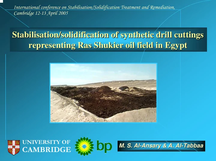
Stabilisation/solidification of synthetic drill cuttings Stabilisation/solidification of synthetic drill cuttings representing Ras Shukier oil field in Egypt representing Ras Shukier oil field in Egypt
UNIVERSITY OF
CAMBRIDGE
- M. S. Al
- M. S. Al-
- Ansary
Ansary & A & A. . Al Al-
- Tabbaa
Tabbaa