
SLIDE 1
Solidification
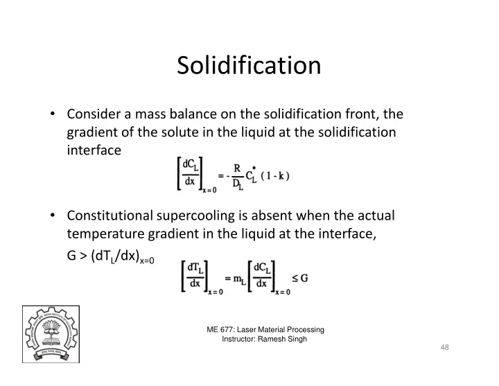
- Consider a mass balance on the solidification front, the
gradient of the solute in the liquid at the solidification interface
ME 677: Laser Material Processing Instructor: Ramesh Singh
- Constitutional supercooling is absent when the actual
temperature gradient in the liquid at the interface, G > (dTL/dx)x=0
48