Sketchup drawing of Trestle Table plan Bottom: Legs and stretcher - - PowerPoint PPT Presentation

sketchup drawing of trestle table plan bottom legs and
SMART_READER_LITE
LIVE PREVIEW

Sketchup drawing of Trestle Table plan Bottom: Legs and stretcher - - PowerPoint PPT Presentation

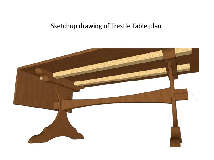
Sketchup drawing of Trestle Table plan Bottom: Legs and stretcher waiting for the table top to be lowered onto the tenons on the top of the legs. Assembled trestle Table with foremost leaf open. final table.jpg Bubinga is oily. Scrub with


slide-1
SLIDE 1

Sketchup drawing of Trestle Table plan

slide-2
SLIDE 2

Bottom: Legs and stretcher waiting for the table top to be lowered

  • nto the tenons on the top of the legs.
slide-3
SLIDE 3

Assembled trestle Table with foremost leaf

  • pen.

final table.jpg

slide-4
SLIDE 4

IMG_0159.jpeg

IMG_0159.jpeg IMG_0159.jpeg

Bubinga is oily. Scrub with Acetone to Release surface

  • ils to be

replaced with hardening tung oil. Eight brushed on coats of floor grade poly-U. Final sanding to 6,000 grit. >Use wipe- no/wipe off gel varnish

slide-5
SLIDE 5

Stock Bubinga

slide-6
SLIDE 6

Trestle table’s base

slide-7
SLIDE 7

Leg Cleat

slide-8
SLIDE 8

Chopping a mortise in the floating tenon for the

  • wedge. The board

was too wide to use a mortising

  • machine. Chop

from both sides and meet in the

  • middle. Making

the 4” deep mortise accept this tenon was difficult.

slide-9
SLIDE 9

Box Joint hinge requires 18” straight hole. Too long to bore. Rip into 6” boards: 6” straight hole OK 8’ ancillary fence Paul’s thickness planer caused tear-out. Justify subsequent measure- ments against the top surface and sand later. Used glue-ready Freud rip blade Six floating tenons /rip joint: Justify against top surface. Acetone before epoxy 19”

slide-10
SLIDE 10

Final hinge Realize the top surface was sanded flat after the hinge was made.

slide-11
SLIDE 11

1” dia. 3/8” dia. 1/2” 3/16” 5/16”

<-Reference Surface, eventual table-top-> Hinge design: the 1” Forstner bit and the 3/8” brad-point bit are aligned to the end and table top surface using brass machinist’s standards.

slide-12
SLIDE 12

Clamped up for hinge boring using Shopsmith horizontal boring capability.

slide-13
SLIDE 13

3” deep 1” diameter hole Forstner bit

slide-14
SLIDE 14

3” deep 1” bore requires a long shank Forstner bit. Without realigning wood or chuck, change to a 3/8” brad point bit for the 6” x 3/8” pivot hole.

slide-15
SLIDE 15

Bored ends ready for routing

slide-16
SLIDE 16

Routing the bored ends with a bull-nosed bit referenced against the top’s surface. Ends are mutually aligned with a dowel through the pivot hole. The 36” stretch is protected on the sides with MDF and routed in small increments.

slide-17
SLIDE 17
slide-18
SLIDE 18

Final bull- nosed router cut before inserting floating tenons and edge-gluing pairs of boards.

slide-19
SLIDE 19

Touching up the hinge with custom-ground carving tool.

Take to industrial surface Sander with the leaves attached by dowels before the final pass.

slide-20
SLIDE 20

Wenge inlay: dado was made with a track saw followed by routing. Note continuous grain across hinge joint.

slide-21
SLIDE 21

Mortised cleats affixed with screws near

  • center. All else

with table-top

  • fasteners. Note

fastener to bring together separating boards.

Mortises to fit on the tenons on the legs

slide-22
SLIDE 22

Leaf extended and locked open with T- track system. Table top is ready to be carried by two strong neighbors into dining room and its awaiting base

slide-23
SLIDE 23

Bottom: Legs and stretcher waiting for the table top to be lowered

  • nto the tenons on the top of the legs.