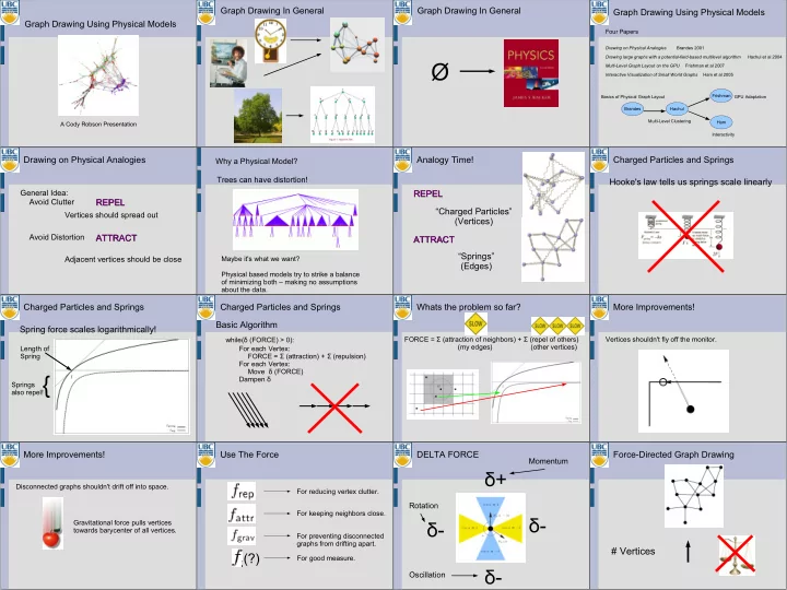

Graph Drawing Using Physical Models
A Cody Robson Presentation
Graph Drawing In General Graph Drawing In General
Ø
Graph Drawing Using Physical Models
Four Papers
Drawing on Physical Analogies Brandes 2001 Drawing large graphs with a potential-field-based multilevel algorithm Hachul et al 2004 Multi-Level Graph Layout on the GPU Frishman et al 2007 Interactive Visualization of Small World Graphs Ham et al 2005 Brandes Hachul Frishman Ham Basics of Physical Graph Layout Multi-Level Clustering GPU Adaptation Interactivity
Drawing on Physical Analogies
General Idea: Avoid Clutter Avoid Distortion Vertices should spread out Adjacent vertices should be close
ATTRACT ATTRACT REPEL REPEL
Trees can have distortion!
Maybe it's what we want? Physical based models try to strike a balance
- f minimizing both – making no assumptions
about the data.
Why a Physical Model?
Analogy Time! REPEL REPEL ATTRACT ATTRACT “Charged Particles” (Vertices) “Springs” (Edges) Charged Particles and Springs Hooke's law tells us springs scale linearly Charged Particles and Springs Spring force scales logarithmically!
Length of Spring Springs also repel!{
Charged Particles and Springs Basic Algorithm
For each Vertex: FORCE = Σ (attraction) + Σ (repulsion) For each Vertex: Move δ (FORCE) Dampen δ while(δ (FORCE) > 0):
Whats the problem so far?
FORCE = Σ (attraction of neighbors) + Σ (repel of others) (my edges) (other vertices)
More Improvements!
Vertices shouldn't fly off the monitor.
More Improvements!
Disconnected graphs shouldn't drift off into space. Gravitational force pulls vertices towards barycenter of all vertices.
Use The Force
(?)
For reducing vertex clutter. For keeping neighbors close. For preventing disconnected graphs from drifting apart. For good measure.
DELTA FORCE
δ+ δ- δ- δ-
Oscillation Rotation Momentum
Force-Directed Graph Drawing