Schedule Date Day Class Title Chapters HW Lab Exam No. Due - - PowerPoint PPT Presentation

schedule
SMART_READER_LITE
LIVE PREVIEW

Schedule Date Day Class Title Chapters HW Lab Exam No. Due - - PowerPoint PPT Presentation

Schedule Date Day Class Title Chapters HW Lab Exam No. Due date Due date 15 Oct Wed 13 Phasors 4.4 EXAM 1 16 Oct Thu 17 Oct Fri Recitation 18 Oct Sat 19 Oct Sun 20 Oct Mon 14 AC Circuit Analysis 4.5 NO LAB 21 Oct


slide-1
SLIDE 1

ECEN 301 Discussion #13 – Phasors 1

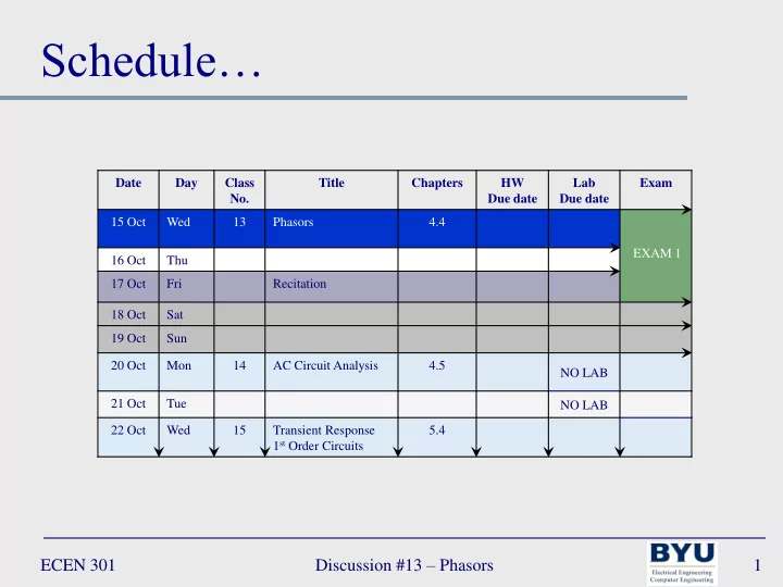
Date Day Class No. Title Chapters HW Due date Lab Due date Exam 15 Oct Wed 13 Phasors 4.4 EXAM 1 16 Oct Thu 17 Oct Fri Recitation 18 Oct Sat 19 Oct Sun 20 Oct Mon 14 AC Circuit Analysis 4.5 NO LAB 21 Oct Tue NO LAB 22 Oct Wed 15 Transient Response 1st Order Circuits 5.4

Schedule…

slide-2
SLIDE 2

ECEN 301 Discussion #13 – Phasors 2

Imaginary

JS-H 1: 16 16 But, exerting all my powers to call upon God to deliver me

  • ut of the power of this enemy which had seized upon me, and

at the very moment when I was ready to sink into despair and abandon myself to destruction—not to an imaginary ruin, but to the power of some actual being from the unseen world, who had such marvelous power as I had never before felt in any being—just at this moment of great alarm, I saw a pillar of light exactly over my head, above the brightness of the sun, which descended gradually until it fell upon me.

slide-3
SLIDE 3

ECEN 301 Discussion #13 – Phasors 3

Lecture 13 – Network Analysis with Capacitors and Inductors

Phasors

slide-4
SLIDE 4

ECEN 301 Discussion #13 – Phasors 4

Euler’s Identity

Appendix A reviews complex numbers

Complex exponential (ejθ) is a point on the complex plane         

  

            A jA A Ae j e j e

j j j

sin cos 1 sin cos sin cos 1 sin cos

2 2

1 1

  • 1

j

  • j

Re Im sinθ cosθ θ

ejθ

slide-5
SLIDE 5

ECEN 301 Discussion #13 – Phasors 5

Phasors

Rewrite the expression for a general sinusoid signal:

} Re{ ) cos(

) (  

 

 

t j

e A t A

Angle (or argument) magnitude

Complex phasor notation for the simplification:

  

j

Ae A t A     ) cos(

NB: The ejwt term is implicit (it is there but not written)

slide-6
SLIDE 6

ECEN 301 Discussion #16 – Frequency Response 6

Frequency Domain

Graphing in the frequency domain: helpful in order to understand Phasors

  • 1.5

0.0 1.5 0.00 2.00 4.00

time x(t)

0.00 3.50

  • 600.0

0.0 600.0 w X(jw)

  • ω

ω π π

cos(ω0t)

π[δ(ω – ω0) + δ(ω – ω0)]

Time domain Frequency domain

slide-7
SLIDE 7

Electromagnetic Spectrum

ECEN 301 Discussion #13 – Phasors 7

slide-8
SLIDE 8

ECEN 301 Discussion #13 – Phasors 8

Phasors

1. Any sinusoidal signal can be represented by either:

 Time-domain form: v(t) = Acos(ωt+θ)  Frequency-domain form: V(jω) = Aejθ = A θ

2. Phasor: a complex number expressed in polar form consisting of:

 Magnitude (A)  Phase angle (θ)

3. Phasors do not explicitly include the sinusoidal frequency (ω) but this information is still important

slide-9
SLIDE 9

ECEN 301 Discussion #13 – Phasors 9

Phasors

 Example1: compute the phasor voltage for the equivalent voltage vs(t)

 v1(t) = 15cos(377t+π/4)  v2(t) = 15cos(377t+π/12)

v1(t)

+ – ~

v2(t)

+ – ~

vs(t)

+ – ~

slide-10
SLIDE 10

ECEN 301 Discussion #13 – Phasors 10

Phasors

 Example1: compute the phasor voltage for the equivalent voltage vs(t)

 v1(t) = 15cos(377t+π/4)  v2(t) = 15cos(377t+π/12)

v1(t)

+ – ~

v2(t)

+ – ~

vs(t)

+ – ~ 1. Write voltages in phasor notation

V e j V V e j V

j j

12 15 15 ) ( 4 15 15 ) (

12 / 2 4 / 1

   

 

     

slide-11
SLIDE 11

ECEN 301 Discussion #13 – Phasors 11

Phasors

 Example1: compute the phasor voltage for the equivalent voltage vs(t)

 v1(t) = 15cos(377t+π/4)  v2(t) = 15cos(377t+π/12) V j j j V V j V 88 . 3 49 . 14 12 sin 15 12 cos 15 ) ( : r rectangula Convert to 12 15 ) (

2 2

                      

v1(t)

+ – ~

v2(t)

+ – ~

vs(t)

+ – ~ 1. Write voltages in phasor notation 2. Convert phasor voltages from polar to rectangular form (see Appendix A) V j j j V V j V 61 . 10 61 . 10 4 sin 15 4 cos 15 ) ( : r rectangula Convert to 4 15 ) (

1 1

                      

slide-12
SLIDE 12

ECEN 301 Discussion #13 – Phasors 12

Phasors

 Example1: compute the phasor voltage for the equivalent voltage vs(t)

 v1(t) = 15cos(377t+π/4)  v2(t) = 15cos(377t+π/12)

v1(t)

+ – ~

v2(t)

+ – ~

vs(t)

+ – ~ 1. Write voltages in phasor notation 2. Convert phasor voltages from polar to rectangular form (see Appendix A) 3. Combine voltages

49 . 14 10 . 25 ) ( ) ( ) (

2 1

j j V j V j VS       

slide-13
SLIDE 13

ECEN 301 Discussion #13 – Phasors 13

Phasors

 Example1: compute the phasor voltage for the equivalent voltage vs(t)

 v1(t) = 15cos(377t+π/4)  v2(t) = 15cos(377t+π/12)

v1(t)

+ – ~

v2(t)

+ – ~

vs(t)

+ – ~ 1. Write voltages in phasor notation 2. Convert phasor voltages from polar to rectangular form (see Appendix A) 3. Combine voltages 4. Convert rectangular back to polar

6 98 . 28 ) ( 6 10 . 25 49 . 14 tan 98 . 28 (14.49) (25.10) r : polar to Convert 49 . 14 10 . 25 ) (

1 2 2

                   

j V j j V

S S

slide-14
SLIDE 14

ECEN 301 Discussion #13 – Phasors 14

Phasors

 Example1: compute the phasor voltage for the equivalent voltage vs(t)

 v1(t) = 15cos(377t+π/4)  v2(t) = 15cos(377t+π/12)

v1(t)

+ – ~

v2(t)

+ – ~

vs(t)

+ – ~ 1. Write voltages in phasor notation 2. Convert phasor voltages from polar to rectangular form (see Appendix A) 3. Combine voltages 4. Convert rectangular back to polar 5. Convert from phasor to time domain

          6 377 cos 98 . 28 ) ( 6 98 . 28 ) (    t t v j V

S S

Bring ωt back NB: the answer is NOT simply the addition of the amplitudes of v1(t) and v2(t) (i.e. 15 + 15), and the addition of their phases (i.e. π/4 + π/12)

slide-15
SLIDE 15

ECEN 301 Discussion #13 – Phasors 15

Phasors

 Example1: compute the phasor voltage for the equivalent voltage vs(t)

 v1(t) = 15cos(377t+π/4)  v2(t) = 15cos(377t+π/12)

v1(t)

+ – ~

v2(t)

+ – ~

vs(t)

+ – ~

          6 377 cos 98 . 28 ) ( 6 98 . 28 ) (    t t v j V

S S

Re Im 14.49 π/6 25.10 Vs(jω)

slide-16
SLIDE 16

ECEN 301 Discussion #13 – Phasors 16

Phasors of Different Frequencies

Superposition of AC signals: when signals do not have the same frequency (ω) the ejωt term in the phasors can no longer be implicit

i1(t)

Load + v – I

i2(t)

2 1 2 1 2 2 1 1 2 1

2 1

) ( ) ( ) ( ) ( ) ( ) (

j j t j j t j j

e A e A e e A e e A j I j I j I t i t i t i        

 

  

NB: ejωt can no longer be implicit

slide-17
SLIDE 17

ECEN 301 Discussion #13 – Phasors 17

Phasors of Different Frequencies

Superposition of AC signals: when signals do not have the same frequency (ω) solve the circuit separately for each different frequency (ω) – then add the individual results

R1 R2

i1(t) vs(t)

+ –

slide-18
SLIDE 18

ECEN 301 Discussion #13 – Phasors 18

Phasors of Different Frequencies

+ R1 – + R2 –

i1(t) vs(t)

+ –  Example2: compute the resistor voltages  is(t) = 0.5cos[2π(100t)] A  vs(t) = 20cos[2π(1000t)] V  R1 = 150Ω, R2 = 50 Ω

slide-19
SLIDE 19

ECEN 301 Discussion #13 – Phasors 19

Phasors of Different Frequencies

+ R1 – + R2 –

i1(t)

1. Since the sources have different frequencies (ω1 = 2π*100) and (ω2 = 2π*1000) use superposition

  • first consider the (ω1 = 2π*100) part of

the circuit

  • When vs(t) = 0 – short circuit

 Example2: compute the resistor voltages

 is(t) = 0.5cos[2π(100t)] A  vs(t) = 20cos[2π(1000t)] V  R1 = 150Ω, R2 = 50 Ω

slide-20
SLIDE 20

ECEN 301 Discussion #13 – Phasors 20

Phasors of Different Frequencies

 Example2: compute the resistor voltages

 is(t) = 0.5cos[2π(100t)] A  vs(t) = 20cos[2π(1000t)] V  R1 = 150Ω, R2 = 50 Ω + R1|| R2 –

i1(t)

1. Since the sources have different frequencies (ω1 = 2π*100) and (ω2 = 2π*1000) use superposition

  • first consider the (ω1 = 2π*100) part of

the circuit

75 . 18 ) 150 ( ) 50 ( ) 150 )( 50 ( 5 . || ) ( ) ( 5 . ) (

2 1 2 1 2 1 2 1

              R R R R I R R I j V j V j I

s s I I s

  

slide-21
SLIDE 21

ECEN 301 Discussion #13 – Phasors 21

Phasors of Different Frequencies

 Example2: compute the resistor voltages

 is(t) = 0.5cos[2π(100t)] A  vs(t) = 20cos[2π(1000t)] V  R1 = 150Ω, R2 = 50 Ω

                   5 5 ) 150 ( ) 50 ( ) 50 ( 20 ) ( 20 ) (

2 1 2 2

R R R V j V j V

s V s

1. Since the sources have different frequencies (ω1 = 2π*100) and (ω2 = 2π*1000) use superposition

  • first consider the (ω1 = 2π*100) part of

the circuit

  • Next consider the (ω2 = 2π*1000) part
  • f the circuit

+ R1 – + R2 –

vs(t)

+ –

15 ) 150 ( ) 50 ( ) 150 ( 20 ) ( 20 ) (

2 1 1 1

           R R R V j V j V

s V s

 

slide-22
SLIDE 22

ECEN 301 Discussion #13 – Phasors 22

Phasors of Different Frequencies

 Example2: compute the resistor voltages

 is(t) = 0.5cos[2π(100t)] A  vs(t) = 20cos[2π(1000t)] V  R1 = 150Ω, R2 = 50 Ω 1. Since the sources have different frequencies (ω1 = 2π*100) and (ω2 = 2π*1000) use superposition

  • first consider the (ω1 = 2π*100) part of the

circuit

  • Next consider the (ω2 = 2π*1000) part of

the circuit

  • Add the two together

)] 1000 ( 2 cos[ 15 )] 100 ( 2 cos[ 75 . 18 ) ( 15 75 . 18 ) ( ) ( ) (

1 1 1 1

t t t v j V j V j V

V I

             )] 1000 ( 2 cos[ 5 )] 100 ( 2 cos[ 75 . 18 ) ( 5 75 . 18 ) ( ) ( ) (

1 2 2 2

t t t v j V j V j V

V I

             + R1 – + R2 –

i1(t) vs(t)

+ –

slide-23
SLIDE 23

ECEN 301 Discussion #13 – Phasors 23

Impedance

Impedance: complex resistance (has no physical significance)

 will allow us to use network analysis methods such as node voltage, mesh current, etc.  Capacitors and inductors act as frequency-dependent resistors vs(t)

+ – ~ R + vR(t) – i(t)

vs(t)

+ – ~ C + vC(t) – i(t)

vs(t)

+ – ~ L + vL(t) – i(t)

Vs(jω)

+ – ~ + VZ(jω) – I(jω) Z

slide-24
SLIDE 24

ECEN 301 Discussion #13 – Phasors 24

Impedance – Resistors

Impedance of a Resistor:

Consider Ohm’s Law in phasor form:

) ( ) (     R A j I A j V

Z Z

 

Vs(jω)

+ – ~ + VZ(jω) – I(jω) Z

) cos( ) ( ) ( ) cos( ) ( t R A R t v t i t A t v

s s

    

Re Im I V Phasor Phasor domain

R j I j V j Z

Z Z R

  ) ( ) ( ) (   

NB: Ohm’s Law works the same in DC and AC

slide-25
SLIDE 25

ECEN 301 Discussion #13 – Phasors 25

Impedance – Inductors

Impedance of an Inductor:

First consider voltage and current in the time-domain

) sin( ) cos( 1 ) ( 1 ) ( ) ( ) ( ) ( t L A d A L d v L t i t v dt t di L t v

L L S L L

          

 

vs(t)

+ – ~ L + vL(t) – i(t) NB: current is shifted 90 from voltage

           2 cos ) sin( ) ( ) cos( ) ( ) (       t L A t L A t i t A t v t v

L L S

slide-26
SLIDE 26

ECEN 301 Discussion #13 – Phasors 26

Impedance – Inductors

Impedance of an Inductor:

Now consider voltage and current in the phasor-domain

2 ) ( ) (          L A j I A j V

Z Z

vs(t)

+ – ~ L + vL(t) – i(t)

           2 cos ) sin( ) ( ) cos( ) ( ) (       t L A t L A t i t A t v t v

L L S

Vs(jω)

+ – ~ + VZ(jω) – I(jω) Z Phasor Phasor

L j j I j V j Z

Z Z L

      ) ( ) ( ) (

Phasor domain Re Im I V

  • π/2
slide-27
SLIDE 27

ECEN 301 Discussion #13 – Phasors 27

Impedance – Capacitors

Impedance of a capacitor:

First consider voltage and current in the time-domain

             

2 cos )] sin( [ )] cos( [ ) ( ) ( ) ( ) ( 1 ) (         t CA t A C t A dt d C dt t dv C t i t v d i C t v

C C S C C

vs(t)

+ – ~ C + vC(t) – i(t)

Vs(jω)

+ – ~ + VZ(jω) – I(jω) Z Phasor Phasor 2 ) ( ) (         CA j I A j V

Z Z

slide-28
SLIDE 28

ECEN 301 Discussion #13 – Phasors 28

Impedance – Capacitors

Impedance of a capacitor:

Next consider voltage and current in the phasor-domain

2 ) ( ) (         CA j I A j V

Z Z

Vs(jω)

+ – ~ + VZ(jω) – I(jω) Z

C j C j C j I j V j Z

Z Z L

       1 2 1 ) ( ) ( ) (       

Phasor domain Re Im I V π/2

j e j

j

1

2 

 

 

slide-29
SLIDE 29

ECEN 301 Discussion #13 – Phasors 29

Impedance

L j j ZL    ) (

R j ZR  ) ( 

+ L – + C – Re Im

  • π/2

π/2 R

  • 1/ωC

ωL

ZR ZC ZL

Phasor domain + R –

C j j ZC   1 ) ( 

Vs(jω)

+ – ~ + VZ(jω) – I(jω) Z

Impedance of resistors, inductors, and capacitors

slide-30
SLIDE 30

ECEN 301 Discussion #13 – Phasors 30

Impedance

) ( ) ( ) ( : general in Impedence    j jX j R j Z  

Re Im

  • π/2

π/2 R

  • 1/ωC

ωL

ZR ZC ZL

Phasor domain

Vs(jω)

+ – ~ + VZ(jω) – I(jω) Z

Impedance of resistors, inductors, and capacitors

AC resistance reactance Not a phasor but a complex number

slide-31
SLIDE 31

ECEN 301 Discussion #13 – Phasors 31

Impedance

Practical capacitors: in practice capacitors contain a real component (represented by a resistive impedance ZR)

 At high frequencies or high capacitances

  • ideal capacitor acts like a short circuit

 At low frequencies or low capacitances

  • ideal capacitor acts like an open circuit

+ C – + R – + C – Re Im

  • π/2
  • 1/ωC

ZC

Re Im

  • π/2

R

  • 1/ωC

ZR ZC

Ideal Capacitor Practical Capacitor NB: the ratio of ZC to ZR is highly frequency dependent

slide-32
SLIDE 32

ECEN 301 Discussion #13 – Phasors 32

Impedance

Practical inductors: in practice inductors contain a real component (represented by a resistive impedance ZR)

 At low frequencies or low inductances ZR has a strong influence

  • Ideal inductor acts like a short circuit

 At high frequencies or high inductances ZL dominates ZR

  • Ideal inductor acts like an open circuit
  • At high frequencies a capacitor is also needed to correctly model a practical inductor

Re Im π/2 ωL

ZL

Re Im π/2 R ωL

ZR ZL

Ideal Inductor Practical Inductor NB: the ratio of ZL to ZR is highly frequency dependent + L – + R – + L –

slide-33
SLIDE 33

ECEN 301 Discussion #13 – Phasors 33

Impedance

Example3: impedance of a practical capacitor

 Find the impedance  ω = 377 rads/s, C = 1nF, R = 1MΩ

+ R – + C – + Z –

slide-34
SLIDE 34

ECEN 301 Discussion #13 – Phasors 34

Impedance

Example3: impedance of a practical capacitor

 Find the impedance  ω = 377 rads/s, C = 1nF, R = 1MΩ

+ R – + C – + Z –

              

) 36 . ( 10 36 . 9 377 . 1 10 ) 10 )( 10 )( 377 ( 1 10 1 ) / 1 ( ) / 1 ( ||

5 6 6 9 6

j j CR j R C j R C j R Z Z Z

C R

  

slide-35
SLIDE 35

ECEN 301 Discussion #13 – Phasors 35

Impedance

Example4: find the equivalent impedance (ZEQ)

ω = 104 rads/s, C = 10uF, R1 = 100Ω, R2 = 50Ω, L = 10mH

ZEQ R2 C R1 L

slide-36
SLIDE 36

ECEN 301 Discussion #13 – Phasors 36

Impedance

Example4: find the equivalent impedance (ZEQ)

ω = 104 rads/s, C = 10uF, R1 = 100Ω, R2 = 50Ω, L = 10mH

ZEQ R2 C R1 L

               

) 37 . 1 ( 81 . 9 62 . 9 92 . 1 5 1 50 ) 50 )( 10 10 )( 10 ( 1 50 1 ) / 1 ( ) / 1 ( ||

6 4 2 2 2 2 2 1

j j j CR j R C j R C j R Z Z Z

C R EQ

  

slide-37
SLIDE 37

ECEN 301 Discussion #13 – Phasors 37

Impedance

Example4: find the equivalent impedance (ZEQ)

ω = 104 rads/s, C = 10uF, R1 = 100Ω, R2 = 50Ω, L = 10mH

                

723 . 2 . 136 38 . 90 92 . 101 62 . 9 92 . 1 ) 10 )( 10 ( 100 ) 37 . 1 ( 81 . 9

2 4 1 1 1

j j j L j R Z Z Z Z

EQ L R EQ

ZEQ R1 L ZEQ1

    ) 37 . 1 ( 81 . 9

1 EQ

Z

NB: at this frequency (ω) the circuit has an inductive impedance (reactance or phase is positive)