
SLIDE 1
SAE Aero Micro Presentation 3: Final Design Proposal NAU Capstone - - PowerPoint PPT Presentation
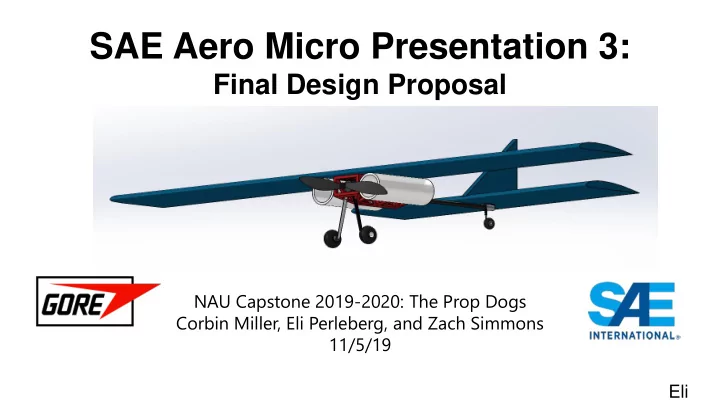
SAE Aero Micro Presentation 3: Final Design Proposal NAU Capstone 2019-2020: The Prop Dogs Corbin Miller, Eli Perleberg, and Zach Simmons 11/5/19 Eli Agenda 1. Project review and description 2. Design description, CAD model, and prototype
SAE INTERNATIONAL 2
c. Wing
Eli
SAE INTERNATIONAL Paper # (if applicable) 3
SAE Aero Micro Class Design: April 3-5, 2020 in Fort Worth, TX Design process to date:
Box and Functional Model
Methodology and Subsystems
& Decision Matrix
Zach
SAE INTERNATIONAL 4
Figure 1: Current State CAD (ISO View)
Wing Drive Fuselage Landing Gear Control
Figure 2: Current State CAD (Front View)
Zach
SAE INTERNATIONAL 5
Subdesign Implementation Details Drive Propeller, motor, ESC, battery, wiring Fuselage Frame geometry and material, drive housing, carbon fiber rod, PVC payload Wing Airfoil selection, chord length, wingspan, aspect ratio, material Landing Gear Geometry, material In-Flight Control Linkages, motors, receiver, controller
Table 1: Current State Model
Zach
SAE INTERNATIONAL 6
Propeller→ Motor→ Electronic Speed Controller (ESC)→ Battery
Given prop chart→ 8x4 or 8x6 prop Selected propeller: APC Electric 8x4.7 SF
Figure 4: APC Electric 8x4.7 SF Figure 3: Propeller Chart
Zach
SAE INTERNATIONAL 7
Propeller→ Motor→ Electronic Speed Controller (ESC)→ Battery Begin with trusted manufacturer: Scorpion Power System Selected Motor: Scorpion HK-2520-1880
Figure 5: Scorpion Motor
Table 2: Motor Selection
Zach
SAE INTERNATIONAL 8
Propeller→ Motor→ Electronic Speed Controller (ESC)→ Battery
Selected ESC: Scorpion Commander 15V 45A ESC w/SBEC Selected Battery: Lumenier 1800mAh 3-cell 35c Lipo Battery
Zach
SAE INTERNATIONAL 9
Drive Part Brand/Model Size Weight (oz) Cost ($) Prop APC Electric SF 8x4.7 8” dia x 4.7” pitch 0.25 2.45 Motor Scorpion HK-2520-1880KV 1” dia, 0.8” length (0.63 in^3) 3.64 80.00 ESC Scorpion Commander 15V 45A ESC SBEC (V3) 2.83”x1.18”x0.32” (1.06 in^3) 1.55 60.00 Battery Lumenier 1800mAh 3s 35c Lipo Battery 4.1”x1.34”x0.79” (4.34 in^3) 4.94 20.00 Total 6.03 in^3 10.38 162.45 Figure 4: APC Electric 8x4.7 SF Figure 5: Scorpion Motor Figure 6: Scorpion ESC Figure 7: Lumenier Battery Table 3: Drive Selection
Zach
SAE INTERNATIONAL 10
Primary functions:
Components:
Figure 8: Fuselage Frame
Zach
SAE INTERNATIONAL 11
Balsa:
ABS:
Selected material→ ABS
Figure 10: ABS Frame Figure 9: Balsa Frame
Zach
SAE INTERNATIONAL 12
CAD model
storage
Figure 12: Fuselage Assembly (Bottom) Figure 11: Fuselage Assembly (Top)
Zach
SAE INTERNATIONAL 13
○ Provides a smooth stall entry for RC planes ○ Flat bottom, simple for manufacturing,
but provides a sufficient amount of lift
○ Square planform area
○ Ailerons with a rectangular wing: easier
and faster
■
Balsa Wood frame and exterior
Figure 13: Airfoil Wing Design
SAE INTERNATIONAL 14
Wing Calculations
Balsa:
Figure 14: Airfoil Wing Design
SAE INTERNATIONAL 15
Tail Dragger Design
supporting wheel
○
Figure 15: Ideal Aircraft Figure 16: Front Wheeled Design Figure 17: Tail Dragger
SAE INTERNATIONAL 16
Primary functions:
Corbin
Components:
Figure 18: Miuzei 10 pcs SG90 9G Servo Motor Kit $18.00 amazon Figure 19: 10 pcs push and pull rods $5.00 amazon Figure 20: 10 pcs control horns
$5.00 amazon
SAE INTERNATIONAL 17
Table 4: Customer Requirements Figure 21: Metal Snaps Figure 22: Estimated Flight time from Ecalc Figure 5: Scorpion Motor Figure 8: Fuselage Design Figure 7: 1800 mAh Lumenier Battery Figure 23: Safety Precaution
Corbin
SAE INTERNATIONAL 18
Corbin
Table 5: Engineering Requirements Table 6: Equation References
SAE INTERNATIONAL 19
Eli 1.
Incapable of generating thrust
2.
Aircraft loses altitude
3.
lack of control and aerodynamics
4.
Plane landing on underbelly
5.
Battery/Motor will combust
6.
Motor will smoke and overheat
Table 7: Failure Mode and Effects Analysis
SAE INTERNATIONAL 20
Future Testing:
○
landing gear, aileron mechanisms, and wing frame
○
Wheeled base with a propellor (aircraft on the ground) ○ Ground checks of ailerons
○
Flying prototypes to prevent failure in the fuselage and frame
○ Justifying that the airfoil is ideal for our design
Resources and equipment
Eli
Table 7a: Failure Mode and Effects Analysis
SAE INTERNATIONAL 21
Total allowance: $2000 Cost of registration: $1100 Total cost $474.29 Funds remaining $425.71
Table 8: Bill of Materials
Corbin
SAE INTERNATIONAL 22
Corbin
SAE INTERNATIONAL 23