
SLIDE 1
Joachim Rodrigues, EIT, LTH, Introduction to Structured VLSI Design jrs@eit.lth.se VHDL II
Introduction to Structured VLSI Design ‐ Recap on Processes, Signals, and Variables
Joachim Rodrigues
Joachim Rodrigues, EIT, LTH, Introduction to Structured VLSI Design jrs@eit.lth.se VHDL II
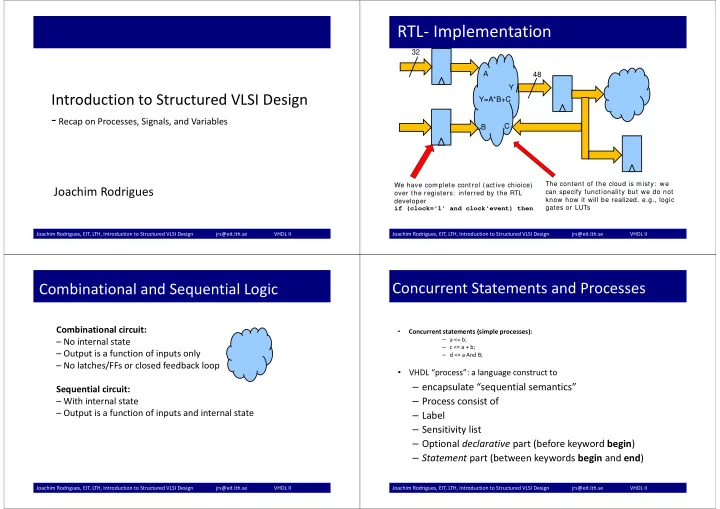
RTL‐ Implementation
32 48 Y=A*B+C A B C Y
We have complete control (active chioice)
- ver the registers: inferred by the RTL
developer if (clock='1' and clock'event) then The content of the cloud is misty: we can specify functionality but we do not know how it will be realized, e.g., logic gates or LUTs
Joachim Rodrigues, EIT, LTH, Introduction to Structured VLSI Design jrs@eit.lth.se VHDL II
Combinational and Sequential Logic
Combinational circuit: – No internal state – Output is a function of inputs only – No latches/FFs or closed feedback loop Sequential circuit: – With internal state – Output is a function of inputs and internal state
Joachim Rodrigues, EIT, LTH, Introduction to Structured VLSI Design jrs@eit.lth.se VHDL II
Concurrent Statements and Processes
- Concurrent statements (simple processes):
– a <= b; – c <= a + b; – d <= a And B;
- VHDL “process”: a language construct to