
SLIDE 1
Rotation About Arbitrary Point other than the Origin
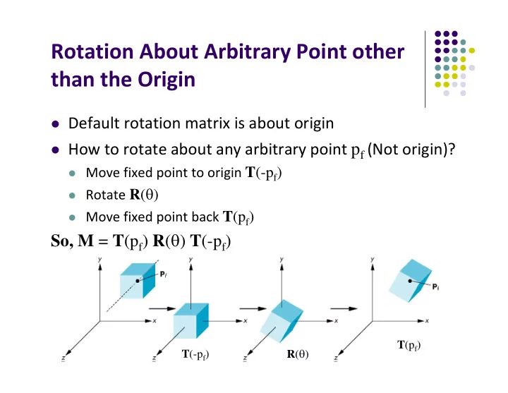
Default rotation matrix is about origin How to rotate about any arbitrary point pf (Not origin)?
Move fixed point to origin T(-pf) Rotate R() Move fixed point back T(pf)
So, M = T(pf) R() T(-pf)
T(pf) T(-pf) R()