robot club toulon mechanical presentation 2019
play

Robot Club Toulon : Mechanical Presentation 2019 V. Gies, V. - PDF document

Robot Club Toulon : Mechanical Presentation 2019 V. Gies, V. Barchasz, J.M. Herve, B. Talaron, C. Albert, G. Borowycz, N. Prouteau, S. Larue, and T. Soriano Universit e de Toulon, Avenue de lUniversit e, 83130 La Garde, France


  1. Robot Club Toulon : Mechanical Presentation 2019 V. Gies, V. Barchasz, J.M. Herve, B. Talaron, C. Albert, G. Borowycz, N. Prouteau, S. Larue, and T. Soriano Universit´ e de Toulon, Avenue de l’Universit´ e, 83130 La Garde, France rct@univ-tln.fr Home page : http://rct.univ-tln.fr 
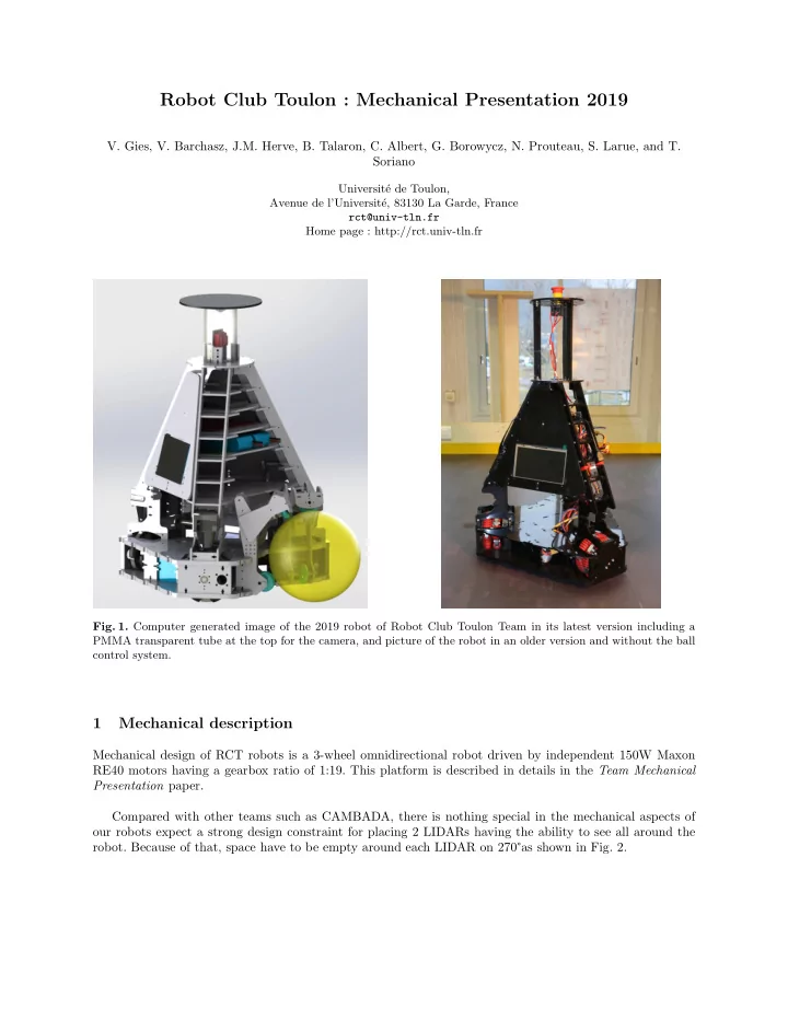
Fig. 1. Computer generated image of the 2019 robot of Robot Club Toulon Team in its latest version including a PMMA transparent tube at the top for the camera, and picture of the robot in an older version and without the ball control system. 1 Mechanical description Mechanical design of RCT robots is a 3-wheel omnidirectional robot driven by independent 150W Maxon RE40 motors having a gearbox ratio of 1:19. This platform is described in details in the Team Mechanical Presentation paper. Compared with other teams such as CAMBADA, there is nothing special in the mechanical aspects of our robots expect a strong design constraint for placing 2 LIDARs having the ability to see all around the robot. Because of that, space have to be empty around each LIDAR on 270 ° as shown in Fig. 2.

  2. 2 Authors Suppressed Due to Excessive Length Fig. 2. Sectional view form top at LIDARs level. LIDARs active zones are in red. Fig. 3. POM base : most of the parts of our robots are made from black POM (even if it is represented as white POM is the rendering), in 3mm, 5mm or 10mm thickness. They are cut using a TROTEC 100R laser cutter at our lab.

  3. Robot Club Toulon : Mechanical Presentation 2019 3 Fig. 4. RCT MSL robots use omnidirectional wheel with polyurethan rollers having a shore of 60. Diameter of the wheel is 127mm. Originally delivered with hard plastic rollers, custom red rollers with grooves were designed with O-rings to improve grip. Fig. 5. Propulsion block including a Maxon RE040 motor with a CUI AMT102 quadrature encoder, and a T5 165mm belt transmission. Maximum speed can be adjusted through the pulley teeth ratio. Axis is an iron one with key for locking pulleys and the wheel.

  4. 4 Authors Suppressed Due to Excessive Length Fig. 6. Motor block assembly including a Maxon RE40 motor, an omnidirectional wheel and two pulley with a T5 belt. All is tied on black POM home-made mechanical parts. Fig. 7. Exploded view of RCT 3-wheels omnidirectional base showing propulsion 4S-5600mAh Li-Po batteries in blue and the 3 propulsion blocks

  5. Robot Club Toulon : Mechanical Presentation 2019 5 Fig. 8. 3-wheel omnidirectional 92 mm thick sandwich base.

  6. 6 Authors Suppressed Due to Excessive Length Fig. 9. Base with the ball control system. It uses omnidirectional free wheels in blue for retaining the ball close to the base and motorized omniwheels in blue for controlling the ball. A spring with damper is also present at the top of the control system, but as not be represented. Fig. 10. Another view of the ball control system with the coilgun kicking system in background. At this stage (January 2019), the kicker is still not finished and will be added soon.

  7. Robot Club Toulon : Mechanical Presentation 2019 7 Fig. 11. Top pyramid of the robot including the embedded PC, display screen, and the peripheral board for driving motors and managing quadrature encoders. This assembly can be removed form the robot very quickly removing only 12 screws. Sick TIM361 LIDARs are in their final position on this view (only 2 LIDARs will be present in the final robot).

  8. 8 Authors Suppressed Due to Excessive Length Fig. 12. Exploded view of the top pyramid of the robot for showing internal board : in red our home designed peripheral controller board able to drive 6 motors and 8 quadrature encoders. In grey, the embedded LattePand Alpha PC is at the top of the pyramid in order to be far from the megnetic pertubations generated by the coil gun. At the lower stage, 2 2650 mAh 4S Li-Po batteries are present for powering the control part of the robot. A TRACO switching regulator is also present for generating 12V, and a small green PCB is a second power regulator for powering different sensors and the peripheral board. The HDMI screen on the side is connected to the PC.

  9. Robot Club Toulon : Mechanical Presentation 2019 9 Fig. 13. Electronic boards in the robot. Fig. 14. Vision system on top of the robot, including a Jevois camera with an omnidirectional mirror. A PMMA transparent cylinder if attaching the mirror which has to be very precisely maintained in order to get a proper image.

  10. 10 Authors Suppressed Due to Excessive Length Fig. 15. Simulation image seen by the Jevois camera of the robot over a black and white checker board. Each square of the checker board pattern has a 20cm side. Robot can be seen at the center of the image. There are some abnormal aberration due to the ray-tracing. Fig. 16. Simulation image seen by the Jevois camera of the robot over a black and white checker board with yellow balls. Left image shows a top view of the field. The right one shows the image from the camera. The more camera is looking to a far distance, the more the balls are distorted.

  11. Robot Club Toulon : Mechanical Presentation 2019 11 Fig. 17. Final assembly of our robot !

Download Presentation
Download Policy: The content available on the website is offered to you 'AS IS' for your personal information and use only. It cannot be commercialized, licensed, or distributed on other websites without prior consent from the author. To download a presentation, simply click this link. If you encounter any difficulties during the download process, it's possible that the publisher has removed the file from their server.

Recommend


More recommend