Recent Advances in Photonic Recent Advances in Photonic effect - - PowerPoint PPT Presentation

recent advances in photonic recent advances in photonic
SMART_READER_LITE
LIVE PREVIEW

Recent Advances in Photonic Recent Advances in Photonic effect - - PowerPoint PPT Presentation

Development of Photonic Network Optical burst switching Next Generation Enhancement of Networks Dynamic (Adaptive) Optical Path Control statistical >10Tb/s multiplexing Photonic MPLS Network Recent Advances in Photonic Recent Advances


slide-1
SLIDE 1

Recent Advances in Photonic Recent Advances in Photonic Networking Technologies Networking Technologies

Nagoya University

Ken-ichi Sato

  • 2005. 2. 24.

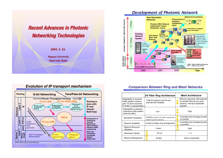
p-to-p WDM Transmission OXC-based Mesh Type Network

OADM : Optical Add/Drop Multiplexer OXC : Optical Cross-connect OXC

Photonic MPLS Router

1999 2001 2003

OADM

!100Gb/s 1T!10Tb/s >10Tb/s

Testbed Experiments since 1998. 640Gb/s OXC System

Photonic MPLS Network employing IP- based distributed control

Tera-bit class large capacity “HIKARI router” (Photonic MPLS router ) presented at Supercomm’ 2001 Photonic MPLS Router IP Packets are mapped

  • nto a bit-stream

Optical burst switching Enhancement of statistical multiplexing effect

Next Generation Networks Existing Network System

Static Optical Path Control Dynamic (Adaptive) Optical Path Control

Year

640Gb/s OXC System NICT National Testbed NW since 2003. 16/32 R-OADM since 2004.

Development of Photonic Network

WDM Ring Network

Introduced in the research networks since 2003. OTN based 43Gb/s transmission system

!

Routing

G-bit Networking Tera/Peta-bit Networking

IP

ATM etc. SDH

Electrical Optical

Wave- length

Routers based

  • n software

routing Routers based

  • n hardware

routing(ASIC) Tbit Routers (IP v6, Hierarchical Addressing etc.)

Routing is done with IP only (Router Multi-hop) Layer 2 Layer 1 Photonic MPLS

Node Throughput Enhancement Traffic Engineering (QoS guarantee)

IP over Optical Path

IP over ATM

Introduction of Underlying Transfer Mechanism which enables effective traffic engineering Mesh-like connection is possible (Router single hop)

MPLS: Multi Protocol Label Switching

MPLS Router Throughput Increase IP over SDH IP over WDM (SDH) Layer 3

Enhancement of Networking Function

Evolution of IP transport mechanism

Comparison Between Ring and Mesh Networks

2/4 Fiber Ring Architecture Mesh Architecture

Minimum planning. Add capacity as needed (Pay as you grow solution). Hot-spot bandwidth upgrade. Adaptability to dynamic traffic patterns (cannot plan 10 years anymore; IP traffic is unpredictable.) Total throughput must be pre- planned and installed. Bandwidth Scalability Limited (two fiber to four fiber up-grade and

multiple ring interconnection).

Controlled and managed growth is possible. Network Scalability Limited (multiple ring arrangement). Controlled and managed growth is possible. Restoration Speed

  • 50 ms

< 1 s Network Management Simple More complicated Network Resource Utilization High Lower Adaptability to distance- insensitive traffic pattern (internet traffic). High Low

slide-2
SLIDE 2

From A. Solheim, Business Briefing, World Markets Research Center, pp. 50-54.

Link Distance and Circuit Length Distribution in Europe

Link Distance Distribution

21% 37% 13% 8% 8% 6% 5% 3% 0% 5% 10% 15% 20% 25% 30% 35% 40%

0-200 200-400 400-600 600-800 800-1000 1000-1200 1200-1400 1400-1600 1600-1800

Link Length (km) Counts (%)

Circuit Length Distribution

9% 20% 16% 12% 12% 15% 9% 3% 3% 0% 5% 10% 15% 20% 25%

0-1000 1000-2000 2000-3000 3000-4000 4000-5000 5000-6000 6000-7000 7000-8000 8000-9000

Circuit Length (km) Counts (%)

Link Distance and Circuit Length Distribution in North America (40 node Model)

> 90%

From J-K Rhee et al., Proc. SPIE, ITCom 2002, vol. 4872, pp. 121-132.

End-to-End Node Cost Reduction

End-to-End node cost ratio

“IP over photonic” to “IP over WDM” PTS WDM LT Intermediate nodes

  • IP over Photonic
  • IP over WDM
  • 2.5 Gbit/s IP router I/F (OC-48c or STM-16)
  • 20 Gbit/s transmission (2.5 Gbit/s 8 )

Cost ratio per 2.5-Gbit/s capacity; PTS : IP router : WDM-LT

3.5 : 1.5 : 2.0 3.0 :0.75 : 2.0

1 2 3 4 5 6 7 8 9 10 1.0 0.8 0.6 0.4 0.2

Number of intermediate nodes Intermediate nodes IP Router IP Router Edge node Edge node Edge node Edge node

Plug-&-Play

  • Self-Recognition of Topology, Resource and

Neighbors!

  • Operation Cost Reduction!

One Click Prompt Service Provisioning

  • Operation Cost Reduction!
  • Enhanced Service Quality

Simple Transmission Layer (Core Network with Optical Nodes Employing Wavelength Routing), and Separation of Transport and Service Operation

  • Operation Cost Reduction
  • Node Cost Reduction

Mesh-like Network based on Distributed Control

  • Network Flexibility Enhancement
  • Efficient Network Resource Utilization

"#$%$&'() "#$%$&'()*+%,$-.) *+%,$-.),'%#) ,'%#)/&%+00'1+&(+ /&%+00'1+&(+

slide-3
SLIDE 3

Node Systems Controlled with GMPLS

PSC: Packet-Switch Capable; MPLS Router L2SC: Layer2-Switch Capable; GbE-SW, ATM-SW FR-SW, MAPOS-SW TDM: Time-Division Multiplex Capable; SDH(VC)- XC LSC: Lambda-Switch Capable; OXC(PXC) FSC: Fiber-Switch Capable

LSP Hierarchy

LSP2FSC Basis3 LSP2LSC Basis3 LSP2TDM Basis3 LSP2PSC Basis3 Fiber Wavelength (Group) Time Slot Cell/Packet

FSC: Fiber Switch Capable, LSC: Lambda Switch Capable, TDM: Time Division Multiplex Capable, PSC: Packet Switch Capable

Each Node Is Treated As an MPLS Label-switching Router (LSR).

LMP LMP Multi-region Network Control Multi-region Network Control GSMP GSMP IS-IS-TE IS-IS-TE OSPF-TE OSPF-TE CR-LDP- EXT CR-LDP- EXT RSVP- TE-EXT RSVP- TE-EXT Multi-region Signaling Multi-region Signaling E-NNI E-NNI I-NNI I-NNI Automatic Service Provisioning Automatic Service Provisioning

Basic Protocol Suit Standardization in progress

Routing

OVPN Photonic IX BoD

Signaling Link Management Switch Control

New Services Will be Standardized Basic Network Management Functions

l-Leased Line Service Multi-grade Leased Line Service

New Service Provisioning with GMPLS Integrated Multi-region Routing Integrated Multi-region Routing All Optical Network Control All Optical Network Control Failure Restoration Failure Restoration Multi-layer Failure Recovery

Progress in GMPLS Protocol Development

Photonic IP Network

Optical level routing (optical path): via OXC Electrical level routing (packet): via LSR

LSR OXC IN OUT OLSP Terminator IN OUT OXC: Optical Cross-Connect LSR: Label Switch Router OLSP Network LSP Network

slide-4
SLIDE 4

Network Design Procedure -Step-1-

  • 1. LSP NW
  • 2. LSP with OXC NW
  • 3. Photonic IP NW

Find LSP Route Add OXC to each node Select a node pair Demands > X%? Establish OLSP for the said node pair, and assign a wavelength to it Yes Any other node pair to be examined? No Yes No End of Step 1 Start

  • Execute cut-through with OLSP

level routing.

  • Smaller LSR size required.
  • Terminate every OLSP
  • n a link-by-link basis.

Input: Physical network topology LSP traffic demand Parameter: OLSP set-up criteria (policy) Node/link cost etc. Output: Total network cost LSP routes OLSP routes OLSP wavelengths

MPLS and Photonic MPLS

MPLS Router Ingress Egress

Label Switch

Ingress Egress Photonic Router

MPLS Photonic MPLS Label is added to each packet. Wavelength label is added to each layer 1 stream.

WP approach VWP approach Wavelength Label

Optical Label Switch

Labeled Packet Labeled Packet Label IP Packet IP Packet IP Packet IP Packet

MPLS and Photonic MPLS

LSP 1 LSP 2 LSP 3 LSP 1 LSP 2 OLSP 1

MPLS- Router Photonic MPLS-Router

OLSP 1 LSP1 and LSP 2 are accommodated within LSP 3. LSP1 and LSP 2 are accommodated within OLSP1.

MPLS- Router

MPLS-router pert multiplexes LSP1 and LSP2 and connects to OLSP1. 45666 45666 466 466 46 46 4 674 674

4889 4889

465666 465666

4886 4886 :666 :666

Avici Cisco Cisco ! Juniper

NTT NTT Cisco Fujitsu Lucent

Juniper Avici Juniper Hitachi Procket Cisco NEC

:669 :669

Moor’s law (x 2/18 months) Traffic Increase (x 2/12 months)

;+<- ;+<- ;+<- ;+<-

=>?%+@) =>?%+@)A#-$B1#CB%) A#-$B1#CB%)2DE DEF? F?3

Progress of Router Throughput

Photonic MPLS Router (NTT) Electrical Router OXC

slide-5
SLIDE 5

1T G 1T H I 1T 1T G 2.5GJ400(40x10) 1T G 250G H I 250G 1T G

3 4 1 2

4FK 4FL Footprint "Number of Cabinets# Power Dissipation

Benefit of Photonic Network

Electrical Router Photonic MPLS Router WDM Transmission + Terabit Electrical Router

Terabit Electrical Router with Cluster Structure Photonic MPLS Router

Photonic MPLS Router

  • Optical cut-through for transit traffic
  • IP routing for terminating traffic

Comparison of Electrical MPLS and Photonic MPLS

Path Label Switched Path

(Label is attached to each packet)

Optical Path

(Label is attached to data stream)

Label Merge Yes Difficult Label Stack Yes Difficult Path State Soft Hard

# of Paths/Link

Can be very large (220=1,048,576) Limited ( < 1,000) Path Bandwidth Any Usually fixed and large (Gb/s) Label Swapping Yes Yes (with wavelength conversion) No (without wavelength conversion) Hit-less Route Change Yes (Make-before-break) No (possible only at electrical level)

Electrical MPLS Photonic MPLS

MPLS Router LRU

Optical amplifier

Wavelength Demultiplexer

Optical coupler DWDM transmission fiber Optical switch IP router/Ethernet switch Connection fiber

Wavelength converter

IP Controller MPLS Controller MPlS Controller Photonic router network manager Photonic MPLS router Manager Optical amplifier DWDM transmission fiber IP router/Ethernet switch Connection fiber Co-operation between OXC and MPLS router. Optical switches fabricated by PLC technologies. Dynamic optical path setup/tear- down.

Configuration of Photonic MPLS Router

Outlook and Specifications of Photonic MPLS Router

Item Item

Throughput Throughput System throughput System throughput UNI UNI Optical switch architecture Optical switch architecture Optical switch Optical switch Wavelength band Wavelength band Optical channel speed Optical channel speed Number of wavelengths Number of wavelengths Number of fiber ports Number of fiber ports Total switch scale Total switch scale Scalability Scalability MPLS router scalability MPLS router scalability

Specifications Specifications

More than 5Gpps (Obtained with wavelength routing and MPLS router) More than 5Gpps (Obtained with wavelength routing and MPLS router) Maximum 2.56 Tbit/s Maximum 2.56 Tbit/s POS, ATM, GEther, etc. POS, ATM, GEther, etc. Delivery and coupling type Delivery and coupling type Planar Lightwave Circuit (PLC) thermo-optical switch Planar Lightwave Circuit (PLC) thermo-optical switch 1550 nm band (C-band) 1550 nm band (C-band) 2.5 Gbit/s (up gradable to 10 Gbit/s) 2.5 Gbit/s (up gradable to 10 Gbit/s) 32 per fiber 32 per fiber 8 input /output pairs (fiber port can be added one by one) 8 input /output pairs (fiber port can be added one by one) 256 x 256 channels 256 x 256 channels The number of available optical channels is expandable up to 256, with 8 wavelengths’ modularity (each switch module accommodates 8 wavelengths.) The number of available optical channels is expandable up to 256, with 8 wavelengths’ modularity (each switch module accommodates 8 wavelengths.) Maximum number of available POS interface is 128. Consists of one to twenty MPLS routers. Maximum number of available POS interface is 128. Consists of one to twenty MPLS routers.

slide-6
SLIDE 6

Photonic Network System

Best Effort (Connectionless) Engineered QoS (Connectionless on Connection Oriented) Guaranteed QoS (Connection Oriented) ATM XC/Switch MPLS Router IP Router Big IP Router Big MPLS Router Photonic MPLS Router

Throughput (Network Scalability)

Network node system and QoS.

IP over ATM OXC/OADM Digital XC

10s 1s 100ms 10ms 1ms 100Ms 1000s 1s 1ms Photonic MPLS Router

Signal length, tb Switching Time tsw (L=0) 100ms

10km 100km 1ms 10ms 1000km 100ms 10,000km

Round trip delay Transmission Distance (L)

Nation wide/Global

h = 0.9

h = tb / (tb + tsw )

h = 0.5 h = N

Target Data Volume Transmitted By 10-Gbit/s signal

Next Generation DVD 30 GB DVD 5 GB CD 650 MB Super High Definition Still Image 12 MB 1TB 1GB 1MB L: Fiber Length

Application area Application area

LAN Metro

Switching time design target & application area

  • A. Sahara et al, ECOC 2004, Th2.6.6 , Sep. 2004

Fast switching technology using GSMP

GSMP(General Switch Management Protocol)

  • Protocol for node control in photonic networks.
  • PLC switch achieves fast switching of less than 6 ms.

The benefit of GSMP A network constructed by various switches can be controlled. Response of optical switch controller with GSMP SW setup time (< 6ms) is achieved in PLC optical switch.

PLC-SW PLC-SW MEMS-SW GMPLS controller GMPLS Controller GSMP-IF GMPLS Controller

  • A. Sahara et al, ECOC 2004, Th2.6.6 , Sep. 2004

107 105 101 103 109 SDH ATM (VPI) 8 bit at UNI 12 bit at NNI 32 bit for IPv4 128 bit for IPv6 Frame Relay (DLCI) 10 bit for 2byte header 23 bit for 4byte header SMDS (VCI) 20 bit MPLS Shim Header Label Ethernet (MAC! ! terminal identification number) 48 bit ! Local Significance WDM IP 1013 Label Stacking

Addressing Space

Global Significance

Layer 1 Layer 2 Layer 3

Available Number of Addresses

slide-7
SLIDE 7

IN OUT

Wavelength

Pulse Generation Multiple Carrier Generation

Wavelength Filter Non-linear Medium

Super-continuum Optical Source Seed Pulses Time

Repetition rate=f0 Bandwidth < f0 Bandwidth > f0

Multi-wavelength Pulse and CW Light Generation with SC Optical Source

f0

f

Filtering out multiple modes Filtering out

  • nly one mode

0.4/f Repetition rate=f0

OPMQ OPMQ

Kubota et al (NTT), CLEO 01 PD, CPD3

d

  • d = 1.5 µm

= 2.3 µm

Optical Loss=3.2dB/kmR1.55µm Zero Dispersion Wavelength=0.81µm

Photonic Crystal Structure Fiber

Micrograph of PM-PCF SC spectra generated with PM-PCF

40 nm

Supercontinuum optical carrier generation with PCF

Photonic Transport Network Testbed (1999-2002)

Hardware

Photonic Node (OPXC, L-REP)

Software

Photonic Network Management

Photonic Transport Network Testbed Applications

Broadband Multimedia Services

N

NTT Yokosuka R&D Center NTT Atsugi R&D Center Route= 150 km Route= 85 km OPXC/PAD L-REP OPXC [PTS]

Miura Peninsula 10 km

slide-8
SLIDE 8

Kyoto Labs. NTT Yokosuka Labs. NTT Tsukuba Labs. NTT Makuhari Labs.

  • To USA

NTT Musashino Labs.

  • NTT R&D facility

Other access point

  • Photonic Empowerment

for GEMnet (by April 20033 Government Supported NICT Photonic Testbed (start at April 2003) Global Lambda Connection

Photonic Testbed Experiments in Japan

GEMnet

STUVWXYTZW[\2]^_`abcdefgh3 STUVWXYTZW[\2]^_`abcdefgh3

]^_R&DiVj abcR&DiVj klmno 2NTT-C3 apqrno OXC OXC OXC SsVt 4u 4u 4u

NTTvwxyz{|}~PTS(Photonic Transport System)

GEMnet2

Empowered by photonic technologies