
SLIDE 1
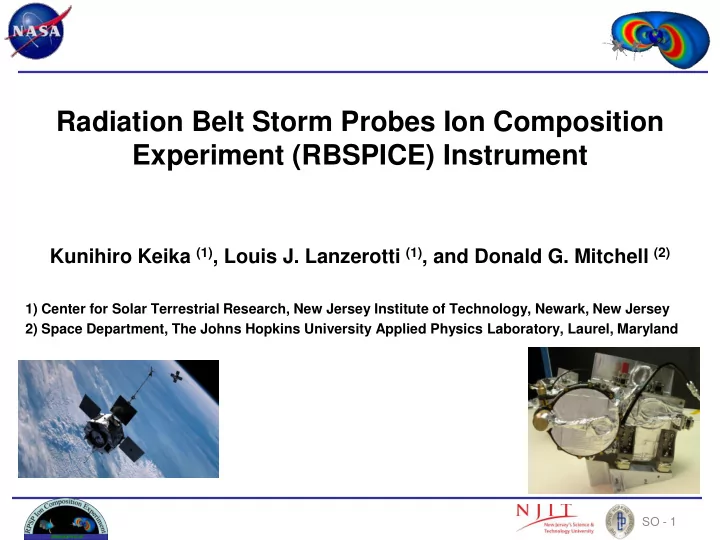
Radiation Belt Storm Probes Ion Composition Experiment (RBSPICE) Instrument
Kunihiro Keika (1), Louis J. Lanzerotti (1), and Donald G. Mitchell (2)
1) Center for Solar Terrestrial Research, New Jersey Institute of Technology, Newark, New Jersey 2) Space Department, The Johns Hopkins University Applied Physics Laboratory, Laurel, Maryland
SO - 1