
SLIDE 1
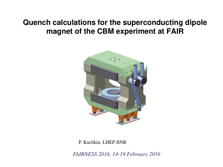
Quench calculations for the superconducting dipole magnet of the CBM experiment at FAIR
- P. Kurilkin, LHEP JINR
Quench calculations for the superconducting dipole magnet of the CBM - - PowerPoint PPT Presentation
Quench calculations for the superconducting dipole magnet of the CBM experiment at FAIR P. Kurilkin, LHEP JINR FAIRNESS 2016, 14-19 February 2016 Content of the talk Introduction Specification of CBM magnet Instantaneous quench
2
somewhere in the winding at a point - this is the problem!
dissipated as heat
point where the quench starts
terminal voltage ( = Vcs current supply) From M. Wilson, 'Pulsed Superconducting Magnets' CERN Academic Training May 2006
the quench starts at a point and then grows in three dimensions via the combined effects of Joule heating and thermal conduction
3
constant
2 m
p
t
From M. Wilson, 'Pulsed Superconducting Magnets' CERN Academic Training May 2006 4
with the winding
magnet, effectively forcing the normal zone to grow more rapidly higher resistance shorter decay time lower temperature rise at the hot spot Note: usually pulse the heater by a capacitor, the high voltages involved raise a conflict between:-
From M. Wilson, 'Pulsed Superconducting Magnets' CERN Academic Training May 2006 5
6
№ п/п Name of the magnet parameters Value 1 Vertically opening angle, deg. ±25 2 Horizontally opening angle, deg ±30 3 Free aperture: vertically (horizontally), m 1,4 (1.8) 4 Distance target- magnet core end, m 1,0 5 Field integral, Tm. 1,0 6 Field integral variation over the whole
≤ 20 7 Duration of operation per year, month. 3 8 Total working time, year 20 11 Crane lifting during assembly, t 30 12 Maximal floor load, t/m2 100 13 Beam height over the floor, m 5,8 The Technical Design Report for the CBM Superconducting Dipole Magnet. http://www.fair-center.eu/fileadmin/ fair/experiments/CBM/TDR/CBMmagnetTDR31102013-nc.pdf
7
Specifications of the superconducting wire Material of SC cable NbTi/Cu Dimension of conductor 2,02x3.25 mm Cu(total)/S.C. ratio 9.1 Insulation Kapton + GF tape Filament diameter < 40 mm Number of filaments ~ 552 Twist pitch 45 mm RRR >100 Critical current @ 4.2K 1330 A @5 T
av = 10 K, Bav=Bmax/2 at t = 0
d av q turn tpp av av q av q d
1
1 1
) ( ) , , ( ) ( 1 ) , , ( 1
av NbTi NbTi av av Cu Cu av NbTi av av Cu av
T A T B RRR A T rl T B RRR rl rl
8
av) is the
E.Floch, P.Swangruber, private communication, GSI, June 20th, 2012
av av turn coil av q av av av av turn coil av av av av q
1 2 1 2
9
ins NbTi Cu ins ins NbTi NbTi Cu Cu av
10
I dI dL I L I L
w w d
2 1 ) ( ) (
Fig.1: (a) Magnet energy and (b) inductances Lw and Ld (b) vs the current. Fig.3: Magnet field in the coil.
The thermal properties of Kapton:
1. http:/cryogenics.nist.gov 2. Dissertation
J. N. Schwerg., “Numerical calculations of Transient Field Effects in Quenching Superconducting Magnets”, Berlin 2010 Fig.2: Simplified model in the CBM magnet coil.
11
Results of 3D GSI (E.Floch, P.Szwangruber) and CIEMATm (P.Kurilkin, F.Toral) quench programs.
for the FAIR Super-FRS Main Dipole”, IEEE Transactions on Applied Superconductivity, 23 No.3 (2013) 4701704
12
3D GSI (E.Floch, P.Szwangruber) 3D CIEMATm (P.Kurilkin, F.Toral) In case of using 1.5-2.1 Ohm resistor 80-86% of 5.15 MJ are dissipated in outside of the coil.
13
3D calculation, Rd=2.1Ohm
14
H.Sato et al., IEEE TRANSACTIONS ON APPLIED SUPERCONDUCTIVITY, VOL. 23, NO. 3, JUNE 2013
L
1 N
Fig.2: Schematic view of the coil cross section and an electrical scheme used in the 1D calculation. Fig.1: Quench protection scheme for CBM magnet, based on the coil heating Yukikazu Iwasa “Case Studies in Superconducting Magnet Design and Operational Issues” 2009
) , ( ) , ( ) (
d h c eff
V I T B R T B R t I I L
2 1 12 2,
L L k M N L I R V L M L L L
c d c ch h c eff
, 2
t L I R R I
c h c
15 Heater parameters:
Material: Cu Size of wire: 2.5x3mm Nturn:35
16 The temperature distributions in the CBM magnet coil cross section during the quench. The heater has 33 turn of Cu wire of 2.02x3.25 mm2 (A) and 3.02x3.25 mm2 (B)
17
18
19