
SLIDE 1
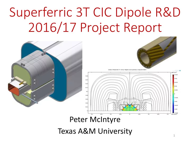
Superferric 3T CIC Dipole R&D 2016/17 Project Report
Peter McIntyre Texas A&M University
1
Superferric 3T CIC Dipole R&D 2016/17 Project Report Peter - - PowerPoint PPT Presentation
Superferric 3T CIC Dipole R&D 2016/17 Project Report Peter McIntyre Texas A&M University 1 CIC Dipole R&D: 8/2017 3/2018 We are developing a 3 T superferric dipole with cable-in- conduit (CIC) superconductor for its
1
incorporating all features required for the CIC dipole.
FY15) and evaluate the coil-winding methods using CIC cable.
for use in a 1.2 m model dipole and in 4 m JLEIC dipoles.
2
3
The culmination of our previous development was fabrication of a 1.2 mockup winding – validating ability to wind CIC and hold tolerances on conductor placement for collider field homogeneity.
15 NbTi/Cu wires are cabled onto a perforated spring tube. The cable is inserted in a sheath tube, and the sheath is drawn
4
with weld puckers: üProblem solved:
5
üInstalled/commissioned 12 m drawbench üDrew perf. tube to final size (4.762 mm) üConfirm roundness,
üForm U-bend with 5 cm radius. üRemove sheath and wires, examine weld, roundness of perf. tube:
6
±.02mm
7
üOrdered from Small Tube Products, Delivered last week. üExcellent uniformity, high-strength üWeld/solder compatibility for splice joints
sheath tube directly onto cable with SS foil overwrap.
üDemonstrated He leak-tight üDemonstrated no damage to wires in cable.
8
Hyper Tech has adapted its continuous-tube-forming process to form and laser-weld sheath tube on CIC cable (SBIR Phase 1). They can prepare km-length CIC cables with no length constraints. ü Validated that CTFF can weld Monel tube onto NbTi cable, no damage. ü Developed the weld process to produce He-tight seam – passed cold-shock pressure tests with He to 600 psig.
10
11
12 3.-0.001” Stainless Steel foil wrapped around without
13
14
15
the 5 cm radius required for the CIC end windings.
work correctly to bend CIC.
must modify forming dies. üFormed U-bends are intact inside, no problems.
16
Calculated joint resistance 0.1 nW Naturally provides for He flow manifold.
17
Flux return FRP structure 125 m CIC cable Fabricate windings Instrumentation Warm measurements
metrology and simulations
18
üFabricated and tested short segments of CIC cable in its final form. üBent the CIC cable in the configuration required for the windings
extracted strands. üA 1.2 m model dipole requires a single 125 m CIC cable. A 4 m dipole requires two 125 m CIC cable segments. üFabricated perforated center tubes and drawn to final size.
19
Design field B0 3 T 6 T 6T graded Coil current 13.7 kA 17.2 kA 18.6 Coil field @ B0 3.5 T 6.9 T 7.1 Bore field @ SS 3.8 T 6.2 T 6.4 # turns in coil 24 54 54 Cable: # strands 15 14 18/10 strand dia. 1.2 mm 1.5 mm 1.39 mm total s.c. area 8 cm2 27 cm2 23 cm2 Flux return size 20 cm 33 cm 35 cm Magnet cost for a CIC dipole is proportional to # turns, flux return size. On that basis, 6 T dipoles would cost ~2.25 x cost of 3 T. Compare to cos q, for which cost ~ B2.
We significantly improved our earlier 6 T CIC design by grading the conductor.
Building/testing a 3 T model dipole would go far toward validating the 6 T cousin.
Half-winding of a 4 m dipole = 27 turns ~ 540 m CIC cable length Priority on completing the development of continuous tube—forming fabrication of sheath tube directly onto cable
22
2 7 12 17 22 2 4 6 8 10
I, kA B, T
Load line
23
dstrand 1.39mm Nstrands 18/10 Cu/Sc 1.2 Dcable 9.94/6.8 8mm Bssl 6.39T Bcab 7.14T Issl 19800A Estored 216kJ/m L 1.10mH/m # Turns /bore 54
30 cm
24
Develop a cost model, based on previous history of s.c. dipoles (SSC, RHIC, HERA, LCH, SIS100) to guide the optimization.
Predict ~$100K per 4 m dipole cold mass.
25
Using what we now know, we made a revised cost projection using actual labor, actual tooling, actual materials and fabrication contracts.
Estimate $155K/dipole for first cold masses.
Based upon our experience to date, I am confident that we should be able to build the arc dipoles and quadrupoles for approximately the budget that we estimated two years ago when we began.
26
27