
SLIDE 1
1
Verilog HDL
Mark Redekopp
2
Purpose
- HDL’s were originally used to model and
simulate hardware before building it
- In the past 20 years, synthesis tools were
developed that can essentially build the hardware from the same description
3
Differences from Software
- Software programming languages are inherently sequential
– Operations executed in sequential order (next, next, next)
- Hardware blocks always run in parallel (at the same time)
– Uses event-driven paradigm (change in inputs causes expression to be evaluated)
- HDL’s provide constructs for both parallel & sequential operation
f = a & b; g = a | b; var = x+y; tmp = d-c;
Software Perform x+y and when that is done assign d-c to tmp Hardware This description models 2 gates working at the same time Event Driven Paradigm: If a or b changes, f and g will be re-evaluated
4
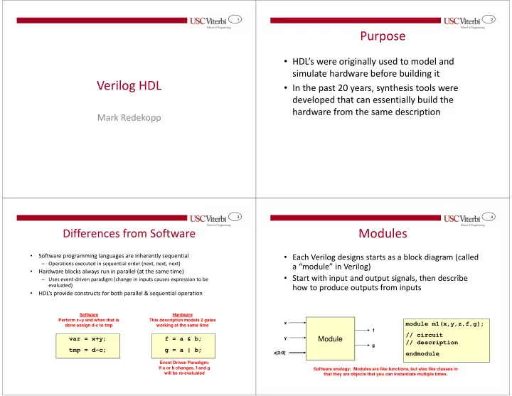
Modules
- Each Verilog designs starts as a block diagram (called
a “module” in Verilog)
- Start with input and output signals, then describe
how to produce outputs from inputs
module m1(x,y,z,f,g); // circuit // description endmodule
Software analogy: Modules are like functions, but also like classes in that they are objects that you can instantiate multiple times.
Module
x y z[2:0] f g