
SLIDE 1
1
Product-Term Based Synthesizable Embedded Programmable Logic Cores
Andy Yan,
- Dr. Steven Wilton
SoC Research Lab, University of British Columbia Vancouver, BC Canada
2
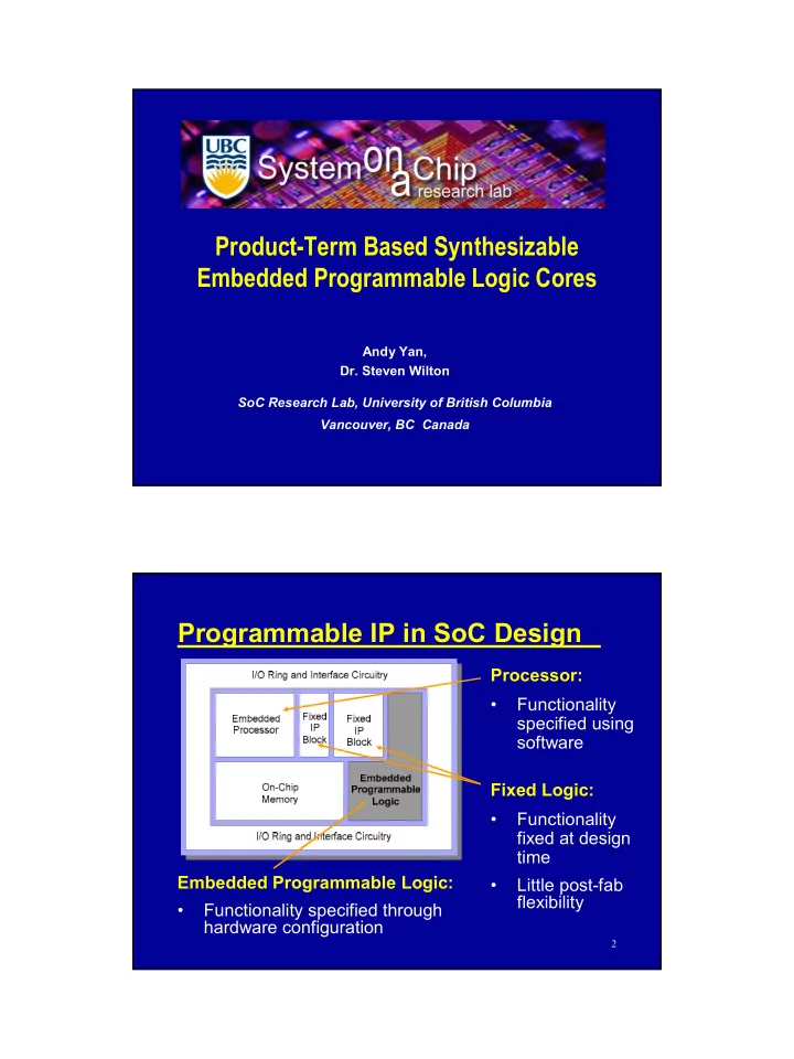
Programmable IP in SoC Design
Fixed Logic:
- Functionality
fixed at design time
- Little post-fab
flexibility Embedded Programmable Logic:
- Functionality specified through
hardware configuration Processor:
- Functionality