
SLIDE 1
HSP Product Presentation Page 1
Basic specifications HSP development evolution Direct Drive technology System overview
Throughput performance Placement head Vision system Board handling Base frame Index drive system
Options
Product Presentation Product Presentation Basic specifications HSP - - PowerPoint PPT Presentation
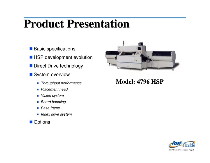
Product Presentation Product Presentation Basic specifications HSP development evolution Direct Drive technology System overview Model: 4796 HSP Throughput performance Placement head Vision system Board handling
HSP Product Presentation Page 1
Basic specifications HSP development evolution Direct Drive technology System overview
Throughput performance Placement head Vision system Board handling Base frame Index drive system
Options
HSP Product Presentation Page 2
Standard machine
"Short" machine
"Large Board" machine
Maximum Speed 36,000cph 36,000cph 36,000cph Feeder Tact Speed 0.11s 0.11s 0.12s-0.13s XY table move at maximum speed 16.8mm 16.8mm ~ 15.0mm Component range
0201-20mm
2
0201-20mm
2
0201-20mm
2
Board size
2x2 (50mmx50mm) 14x18 (356x457) 2x2 (50mmx50mm) 14x18 (356x457) 2x2 (50mmx50mm) 18x20 (457x508)
Feeder capacity 160
(two carriages of 80)
80
(two carriages of 40)
160
(two carriages of 80)
Dimensions
L: 237in (6.0m) W: 79in (2.0m) 3800kg L: 146in (3.7m) W: 79in (2.0m) 3500kg L: 237in (6.0m) W: 83in (2.1m) 4200kg
HSP Product Presentation Page 3
Direct Drive Technology Theta Driver Technology
Model 4760/65 Model 4780/82/85 Model 4795/96 Model 4790/91/92
HSP Product Presentation Page 4
4760 HSP
14,400cph 10”x13” 3 noz / 18 heads Mechanical Center 100 feeders Intro: 1989
4765 HSP
14,400cph 18”x20”
Intro: 1990
4780 HSP
14,400cph 10”x13” 4 noz / 16 heads Vision Center 100 feeders Intro: 1990
4782 HSP
14,400cph
Intro: 1990
4785 HSP
14,400cph 18”x20” 4 noz / 24 heads
Intro: 1991
4790 HSP
25,000cph 18”x20” 6 noz / 24 heads Vision 160 feeders Intro: 1993
4791/4792 HSP
29,000cph
Intro: 1994/1996
4795
36,000cph 10”x13” 5 noz / 16 heads Vision 160 or 80 feeders Intro: 1995
4796B/R
36,000cph 14”x18”
Intro: 1996
Direct Drive Technology
4796L
36,000cph 18”x20”
Intro: 1999
HSP Product Presentation Page 5
Theta Driver Technology... Theta Driver Technology...
5 6 7 8 9 10 11 12 13 14 15 16 1 2 3 4 PICK Component Recognition PLACE engage rotate disengage Position # 6 5 6 7 8 9 10 11 12 13 14 15 16 1 2 3 4 Rotate component
HSP Product Presentation Page 6
Theta correction is done “on-the- fly”, allowing more time to make corrections for larger parts. Result: Faster large part placement speed. Lack of metal-to-metal contact means there are far fewer “wear” issues (loss of accuracy, etc.) compared to theta driver systems Direct Drive technology means...
5 6 7 8 9 10 11 12 13 14 15 16 1 2 3 4 PICK Component Recognition Rotate component PLACE
HSP Product Presentation Page 7
0.05 0.1 0.15 0.2 0.25 0.3
1005 1608 2125 3216 Mini-mold MELF Tant A Tant B Tant C Tant D
SOP8 SOP16 SOP28 SOJ28
MVIIf FCP-642 CM86C 4796 HSP
Fast placement of leaded components
in practice, SOIC16
placed at 36,000/hr
16.8mm XY table move at maximum tact speed No speed loss due to nozzle change or theta orientation of component
speed as much as 50%!
4796 HSP provides fast placement of large components
Placement Tact Speed by Component Type
HSP Product Presentation Page 8
Features
Motor resolution is 0.007 degrees Motor is programmable in 0.01 degree
increments
Vacuum is turned off whenever a
“component not present” error message is indicated by the machine.
Motor’s long life is enhanced by the fact
that it is not moving a load (mass)
Requires minimal maintenance Quick release nozzles save maintenance
and set up time
Available nozzle types…
HSP Product Presentation Page 9
Interface MPU Motor Drive Circuit MOTOR Interface MPU Motor Drive Circuit MOTOR Hd # 1 Hd # 2 Hd # 16 Serial Bus SLIDE CONTACT (Slip ring) Machine Control Unit UNIT DRIVER
HSP Product Presentation Page 10
Features
Vision processor designed by
SANYO.
256 level gray scale. Fiber-optic
lighting units with frontlighting & backlighting capability.
Line sensor: serves two purposes…
(a) to check for missing or “out of spec” components, and (b) to feed true component thickness information back to the Z axis control system
High Mag Low Mag Lenses Frontlighting Backlighting
Single camera assembly housing two cameras (high/low mag)
HSP Product Presentation Page 11
Additional features
Automatic correction: fiducial
“gain” & “level” can be automatically adjusted by the machine
Placement speed test: can be
used to determine the maximum allowable placement speed for any component.
Vision errors: past vision
recognition errors may be displayed on the vision monitor
Component recognition test:
used to check the validity of component library vision parameters.
One image displayed Vision parameters are gradually adjusted until the image is recognized.. 4 images displayed 16 images displayed
HSP Product Presentation Page 12
Features
Programmable width control: XY
table and conveyor width is automatically adjusted when a pattern program change is made.
Auto board thickness: board support
pin height is automatically adjusted by the machine when a program change is implemented
Transfer direction (left-to-right, right-to-
left) is easily configurable on the manufacturing floor
Boards are positioned in the table
using top, front, left-edge mechanical registration.
Special modifications are available for
unique applications (ex. ceramic, flex, PCMCIA, etc)
XY positioning table
HSP Product Presentation Page 13
Features
Specifically designed to absorb
and/or safely dissipate vibration forces
Precision ground and assembled
to minimize tolerances between adjoining mounted assemblies
Upper base frame
HSP Product Presentation Page 14
Features
Counter-balanced cam system provides
smooth operation at fast speeds
Moving assemblies housed in one sealed oil-
bath gearbox to simplify maintenance
720 degree cam drives turret at two times
the machine indexing speed (to extend the useful life of the machine)
Raw machine torque Balancing torque Torque with counter-balance
Inside the upper cavity of machine
HSP Product Presentation Page 15
Operation
Servo controlled Placement head Z height is controlled by
limiting how far down the head goes each time
Performed at the Pick and Place location Feedback loop is tied with the Line Sensor
to their true thickness
Motor driven stroke-depth adjustment
Z axis control mechanism
HSP Product Presentation Page 16
While the machine is picking parts, it automatically updates the pick location based on vision recognition data… this is critical for 0201 or 0402 component handling.
X axis is adjusted by moving the feeder
carriage left or right
Y axis is adjusted by slightly rotating the
placement head
Z axis is adjusted by the Z axis control
mechanism
A small rotation of the head provides a Y axis translation, as seen between the dotted lines below.
Before After
Once the Y axis correction is made, the XY table and/or feeder axis adjusts itself to compensate for this small change in the Y axis coordinate.
HSP Product Presentation Page 17
X-Axis CPK (Serial # 10000 - 10221)
0.00 0.50 1.00 1.50 2.00 2.50 3.00 3.50 4.00 1 15 29 43 57 71 85 99 113 127 141 155 169 183 197 211
Y-Axis CPK (Serial # 10000 - 10221)
0.00 0.50 1.00 1.50 2.00 2.50 3.00 3.50 4.00 1 15 29 43 57 71 85 99 113 127 141 155 169 183 197 211
Testing is performed at the factory, prior to shipment
A record of performance,
called the “Delivery Inspection Results” report (for each machine) is kept at Universal. A duplicate record is shipped with the machine.
Specification
Upper/lower limit: X & Y axis:
± 0.10mm
Cpk: > 1.3
Cpk average results
X & Y axis: ~ 2.0 (or 6 Sigma)
HSP Product Presentation Page 18
Why is this machine so well equipped to handle them?
Nozzles are specially designed to provide
secure and accurate handling Handling speed is controlled at the pick, place, turret, recognition and XY table to provide optimum accuracy and reliability Center of component picking is maintained by automatic updating of X and Y axis to prevent miss-picks and waste Feeders are single stroked, and cam actuated to provide smooth operation
Z-axis control is done by limiting
placement head downward stroke depth to provide smooth pick and place operations
0603 (1608) 0402 (1005) 0201 (0603)
HSP Product Presentation Page 19
Tape Feeders
Available for 8mm, 12mm, 16mm, 24mm and
32mm tape
Special feeders available for 0201 chips Minimal maintenance required
Bulk Feeders
Available for 0402, 0603 and 0805 capacitors Resistor feeders are in development No special programming required Large capacity Same feeder is used on older model 479x
models
HSP Product Presentation Page 20
Bulk Feeder Operation
Operates like a tape feeder No pneumatics or electrical actuation Constant supply of components at pick point
chute onto the belt track
During operation, machine indexes the feeder here Magnet keeps component in place until it is picked by nozzle
move down the track to the pick point
HSP Product Presentation Page 21
Feeder handling accessories
Set-up cart: can accommodate up to 80
8mm tape or bulk feeders. Used (primarily) for off-line set up.
Storage cart: has three shelves and can
accommodate up to 180 8mm tape or bulk feeders.
Feeder reload tool: a bench mounted tool
used to simplify component reel replacement by holding feeder in one position while work is done
Set-up cart Storage cart Reload Tool
HSP Product Presentation Page 22
Bank Feeder Change (BFC)
Fast product changeover change all feeders on the machine
in less than 5 minutes!
Complete product change
(feeders) in minutes
feeder pallet docking stations and
set-up carts available
Available for 4796R Model Only!
Feeder Pallet on Feeder Cart Feeder Pallet Docking Station
HSP Product Presentation Page 23
Transfer/Inspect Switches
Switches are mounted to input and
Boards can be stopped on input or
Auto Board Length
XY table board length mechanism
is is automatically adjusted by the machine when a program change is implemented
Transfer / Inspect Switch - Output side Auto Board Length lever Available for 4796R Model Only!
HSP Product Presentation Page 24
Barcode Validation System (BVS)
Uses “smart feeders” for storage of data
start of production runs
consists of two parts:
(a) machine hardware and software (b) off-line feeder set-up station
Scanning a reel Off-line set-up station Read/write unit mounted in machine feeder area
HSP Product Presentation Page 25
Barcode Product Change (BPC)
automatic changing of current pattern
information based on incoming board barcode
Generic Equipment Model (GEM) Protocol
industry standard machine
communication protocol, carried out
compliance is based on SEMI International Standard E30-93
Barcode Product Change scanning operation
HSP Product Presentation Page 26
HSP UPS Software
provides a common
programming interface among Universal’s line of SM placement machines
CAD translation CDI capability Optimization and Simulation
HSP Product Presentation Page 27
Component Library Data Teaching
Component vision parameters
may be automatically taught using the machine’s component recognition camera system
no need to measure components
by hand
Pattern Program Coordinate Teaching
XY locations on the circuit board
may be automatically taught using the machine’s downward looking camera system
View on monitor (example) View on monitor (example) MCP screen