preface
play

Preface There are more slides here than will be used in lectures. - PDF document

Preface There are more slides here than will be used in lectures. The slides not covered will be listed on the website. At least 10 minutes or so of each lecture will be devoted to example material, including pre- vious exam questions, for


  1. Preface There are more slides here than will be used in lectures. The slides not covered will be listed on the website. At least 10 minutes or so of each lecture will be devoted to example material, including pre- vious exam questions, for which there are no slides in this handout. 1

  2. Books related to the course Suggested books include: W.Ditch. ‘Microelectronic Systems, A practi- cal approach.’ Edward Arnold. The final chap- ters with details of the Z80 and 6502 are not relevant to this course. Floyd. ‘Digital Fundamentals’ Prentice Hall International. T.J. Stoneham. ‘Digital Logic Techniques’ Chapman and Hall. This is a basic book and relates more to the previous course on Digital Electronics. Randy H Katz. ‘Contemporary logic design.’ 2

  3. A Broadside Register Clock Broadside D Q register N N Clock Q0 D D0 Q1 D1 D Q2 D2 D Q(N-1) D(N-1) D 3

  4. A broadside two-to-one multiplexor Select N N DT Y DF N MUX2 Select DT0 Y0 DF0 DT1 Y1 DF1 DT(N-1) Y(N-1) DF(N-1) 4

  5. A dual port register file N N Data out A Data in Read Address A Write Address A A N Data out B clock Read Address B A 5

  6. Read Only Memory (ROM) Address In Addr Data Out Data A ROM N PROM Enable Input E or (active low) The ROM contents EPROM are placed inside during manufacture or field programming. The ROM takes A address bits named A0 to A<A-1> and produces data words of N bits wide. For example, if A=5 and D=8 then the ROM contains 2**5 which is 32 locations of 8 bits each. The address lines are called A0, A1, A2, A3, A4 and the data lines D0, D1, ... D7 Access Time Enable Input (active low) Address In High-Z High-Z Data Out Valid data Ouput Turnon Time The ROM’s outputs are high impedance unless the enable input is asserted (low). After the enable is low the output drivers turn on. When the address has been stable sufficiently long, valid data from that address comes out. 6

  7. Address In Addr A Data In and Out Enable Input Data E RAM (active low) N Read or write R/Wb mode select Read Cycle - Like the ROM Read or write mode select Enable Input (active low) Address In High-Z High-Z Data Bus Valid data Write Cycle - Data stored internally Read or write mode select Enable Input (active low) Address In High-Z Data Bus High-Z Data must be valid here to be stored. 7

  8. Unlike the edge-triggered flip-flop, the transparent latch passes data through in a transparent way when its enable input is high. When its enable input is low, the output stays at the current value. D Q D Q G G Transparent latch schematic symbol Transparent latch implemented from gates. output enable D D D D D D Data G G G G G G WE* Binary to unary decoder CE* Address Input 8

  9. MAddr Multiplexed Address In A Data In and Out RAS Data Row Address Strobe (RAS) DRAM N CAS Row Address Strobe (CAS) Read or write R/Wb mode select Read Cycle (write is similar) Read or write mode select Row Address Strobe (RAS) Row Address Strobe (CAS) Multiplexed Address Row Address Col Address High-Z High-Z Data Bus Valid data A DRAM has a multiplexed address bus and the address is presented in two halves, known as row and column addresses. So the capacity is 4**A x D. A 4 Mbit DRAM might have A=10 and D=4. When a processor (or its cache) wishes to read many locations in sequence, only one row address needs be given and multiple col addresses can be given quickly to access data in the same row. This is known as ‘page mode’ access. EDO (extended data out) DRAM is now quite common. This guarantees data to be valid for an exteneded period after CAS, thus helping system timing design at high CAS rates.
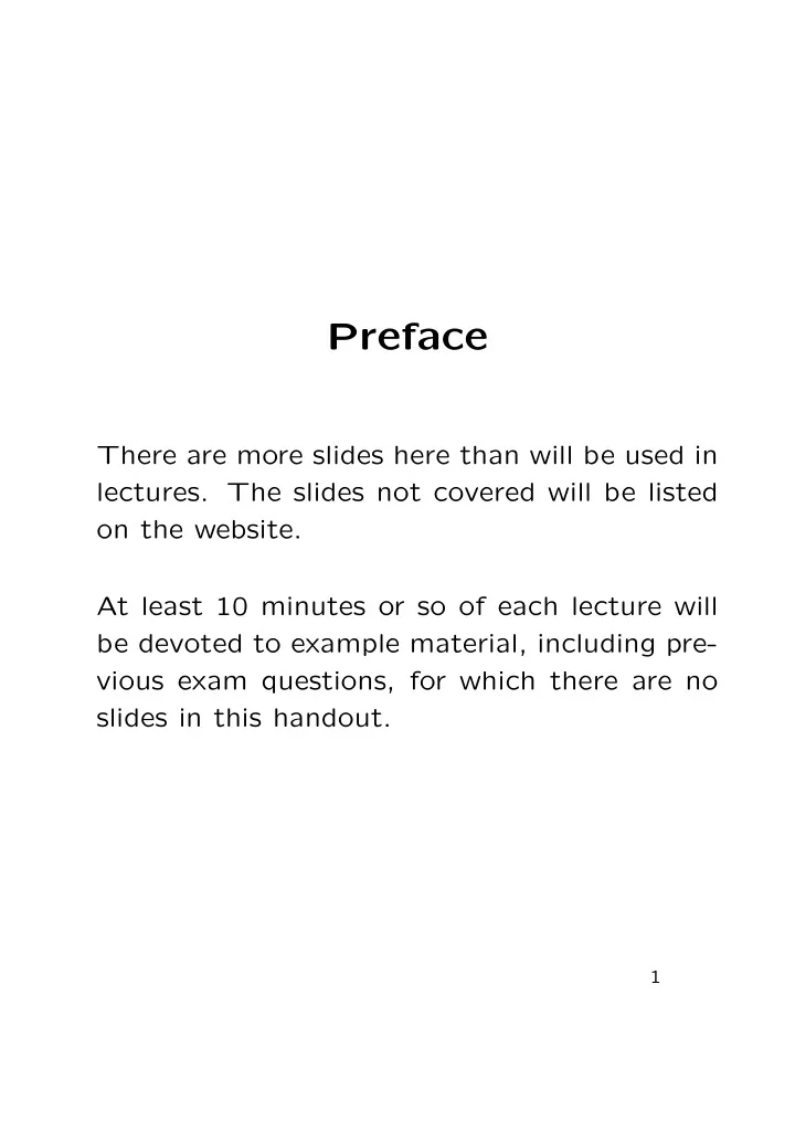
 Refresh Cycle - must happen sufficiently often! Row Address Strobe (RAS) Row Address Strobe (CAS) No data enters or leaves the DRAM during refresh, so it ‘eats memory bandwidth’. Typically 512 cycles of refresh must be done every 8 milliseconds. 9

  10. Crystal oscillator clock source 1M 33pF 33pF Ground RC oscillator clock source R Vo C Ground Vin 10

  11. Clock multiplication and distribution Outside Inside the the PLL Circuit chip chip 264 MHz VCO External clock Divide 8 input 33 MHz Clock distribution tree Power-on reset Supply R Active low Reset output Vo Vi C Ground 11

  12. Driving a heavy current or high-voltage load High Voltage Supply EMF diode Control input Power transistor R Ground 12

  13. Debouncer circuit for a two-pole switch +5Volt supply rail Pullup Resistors Output Switch A B Gnd Bounces A B Output 13

  14. ALU and flags register Function Code 4 Carry In A-input N Output ALU N B-input N C N Flags register Z V Flags Clock 14

  15. ALU and register file Carry In A-input A 8 Output 8 bit ALU 8 B-input B Carry Out 8 Function Code D Register file 16 registers Q Din of 8 bits 8 A 4 FUNCTION GEN for F code 4 bit 4 counter Clock source Zero FUNCTION GEN detect for A input 15

  16. Logic Symbol Data System Clock N Address Reset Input R A Interrupt Request I Operation Opreq Request Read/Notwrite R/Wb Microprocessor Wait W Internal Structure Block Diagram Addresses Write Clock System Clock Dual Port Register File Function code Load or Store Operation Request ALU Read/notwrite MUX Data Bus Bus Control Execution Unit Control Unit Clock Clock Instruction IR Register OPERAND EA Execution address incrementor Instruction Mux 2 Decoder Reset MUX2 Clock PC Control Wires To Program Address Bus All Other Sections Counter Reset 16

  17. Broadside latch VCC D0 Light emitting diodes Part of data D1 D Q (LEDs) bus D2 D3 Pullup D4 resistors D5 Switches Microprocessor Broadside tri-state GND R/Wbar OPREQ Read from switches A12 A13 Part of address bus Write to A14 leds A15 Example of memory address decode and simple LED and switch interfacing for programmed IO (PIO) to a microprocessor. 17

  18. A small computer Clock Address bus Reset Data bus (16 bits) (8 bits) Register File (including PC) D0-7 R/Wb Memory Map A15 Execution Control decoder circuit Unit A14 Unit + ALU A13 Often a ‘PAL’ single chip device. (Micro-)Processor A0-13 Memory D0-7 R/Wb R/Wb Static RAM 16 kByte RAM_ENABLE_BAR Enb A0-9 D0-7 1 K Byte ROM ROM_ENABLE_BAR Read Only Memory Enb R/Wb R/Wb D0-7 UART A0-2 Serial Port UART_ENABLE_BAR Enb Rs232 Serial Connection 18

  19. PC Motherboard, 1997 vintage Main memory DRAM PSU CACHE RAM SIMM 4 SIMM 3 SIMM 2 KYBD SIMM 1 USB IDE-1 COM1 IDE-2 COM2 PCI1 Floppy IDE & Cache PRINTER Floppy Control PCI2 BIOS ROM PCI3 Pentium General CPU glue ISA 16 BIT BATTERY SLOTS Clock Regulator 19

  20. Parallel Port Interface Logic Strobe Address Data Acknowledge CPU Busy BUS SIDE Parallel Data r/wbar Read/Writebar /cs device select Parallel Port D25 Parallel (Centronix) Port Valid Data For Transfer To Peripheral Device Parallel Data Strobe_bar Acknowledge Busy Ready for next data 20 Flow control: New data is not sent while the busy wire is high.

  21. Serial Port (UART) Voltage convertors Serial Output Address 25-Way D connector Serial Input for Serial Port. Data Most computers just use a 9 way connector Int Interrupt these days. Read/Writebar r/wbar Baud Rate /cs chip select Generator LOGIC 1 DO D1 D2 D7 D3 D4 D5 D6 LOGIC 0 Start Stop Bit Bit (one) (zero) Flow control: New data can be sent at any time unless either: additional signals are used to indicate clear to send or a software protocol is defined to run on top (Xon/Xoff) by reserving certain of the bytes. 21

  22. Keyboard and/or PS/2 port +5 Volt Fuse 4 3 5 2 Power wire 6 1 Clock wire Data Wire PS/2 Keyboard/Mouse Cable Ground wires 1. Clock 2. Ground 3. Data 4. Spare PS/2 5. Power +5Volts Connector 6. Spare Ground 22

  23. Canonical synchronous FSM Clock Moore Outputs Inputs Mealy Outputs M FSM Moore Outputs Clock Inputs STATE FLOPS Q0 I0 D I1 Q1 D I2 LOOP-FREE COMBINATORIAL Q2 D LOGIC BLOCK I(M-1) Mealy Outputs D LOOP-FREE COMBINATORIAL LOGIC BLOCK CURRENT STATE FEEDBACK LOOP-FREE COMBINATORIAL LOGIC BLOCK 23

  24. Timing Specifications Data in Q oiutput D Q Clock Clock Hold time Data in Setup time Q oiutput Propagation delay 24

  25. Typical nature of a critical path A D Q B C D D Q Clock Clock A B C D Setup Margin Period = 1/F 25

  26. Johnson counters Q1 Q2 Q3 D QA D Q2 D Q3 Q1 Q2 Q3 Clock 26

  27. Pipelining An output Data in D Q D Q Another input Yet another output D Q D Q Yet another input Another output still D Q D Q Large loop-free combinatorial logic function Synchronous global clock signal Desired logic function D Q An output Data in D Q D Q D Q Another input Yet another output D Q D Q D Q Yet another input Another output still D Q D Q D Q Loop-free combinatorial logic Loop-free combinatorial logic Synchronous global clock function - second half function - first half signal Desired logic function - pipelined version. 27

  28. Cascading FSMs Clock Moore Outputs Inputs Mealy Outputs FSM Moore Inputs Mealy FSM Moore Outputs Inputs Mealy Outputs FSM 28

Download Presentation
Download Policy: The content available on the website is offered to you 'AS IS' for your personal information and use only. It cannot be commercialized, licensed, or distributed on other websites without prior consent from the author. To download a presentation, simply click this link. If you encounter any difficulties during the download process, it's possible that the publisher has removed the file from their server.

Recommend


More recommend