
SLIDE 1
PQM4000 and PQM4000RGW
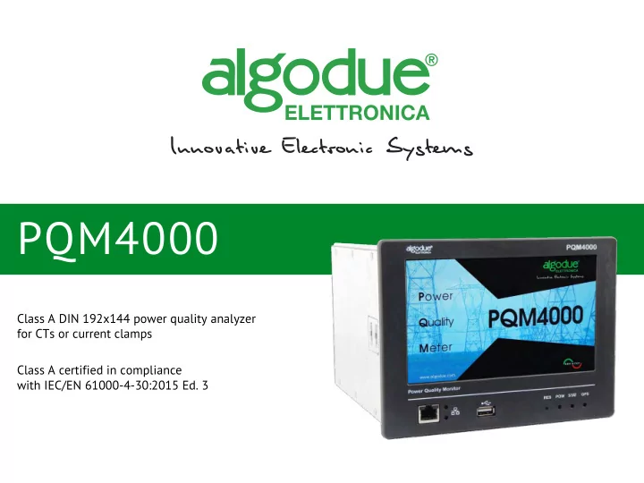
Class A DIN 192x144 power quality analyzer for CTs or current clamps Class A certified in compliance with IEC/EN 61000-4-30:2015 Ed. 3
PQM4000 PQM4000 and PQM4000RGW Class A DIN 192x144 power quality - - PowerPoint PPT Presentation
PQM4000 PQM4000 and PQM4000RGW Class A DIN 192x144 power quality analyzer for CTs or current clamps Class A certified in compliance with IEC/EN 61000-4-30:2015 Ed. 3 APPLICATIONS PQM4000 is connected to networks and facilities to monitor:
Class A DIN 192x144 power quality analyzer for CTs or current clamps Class A certified in compliance with IEC/EN 61000-4-30:2015 Ed. 3
2
Power quality Critical processes even in remote mode Harmonics and interharmonics in cases of power quality problems Type and timing of faults on energy supply Power quality standards according to EN 50160 and issuing a printable report
PQM4000 is connected to networks and facilities to monitor:
Quality analysis according to Class A EN61000-4-30: 2015 Measurements of harmonics and interharmonics according to EN61000-4-7 Flicker measurement according to EN61000-4-15 and IEEE1453 Transients capturing Communication, management and monitoring measuring remotely via ETHERNET High data recording capacity 16GB Touch screen graphic functions
3
Voltage and current additional channels compared to other three phase devices on the market: up to 9 channels, 4 voltage inputs and 5 current inputs PQM4000: current inputs for CT or current clamps to ensure the accuracy of measurement Continuous monitoring of the metering parameters related to power quality for energy characteristics Simultaneous recording of events, Min / AVG / Max values and energy meters in 16Gb memory Various possibilities of data transmission: Ethernet, WIFI, Modbus RTU / TCP, USB Web interface easy to use and available in Italian, English, French, German and Spanish Graphical and table display of the measured data Automatic data transferring to FTP servers operated by frequency event or daily pre-programmed at fixed times Energy pulse generation on digital output according to EN 62053-31 NTP time synchronization (default) or resolution to 1ms with GPS synchronization (option)
4
5
OVERALL AND MOUNTING:
The instrument is for panel mount 192x144 DIN size. The instrument is provided with a touch screen display and an USB port on front panel. The USB port supports USB flash drives for data transferring (recorded data) or upload of device new firmware. Bundled USB pen drive supplied with installation kit for EN50160 analysis. The instrument is provided with two ETHERNET communication ports: 1 front port for a quick instrument connection to a PC 1 rear port for data reading and management in remote mode
6
Back of the instrument
REAR CONNECTION: COMUNICATIONS AND I/O
GENERAL FEATURES
Inputs & Outputs The instrument is provided with digital inputs, outputs and analog
WIFI Port A WIFI port is provided for a quick instrument connection in wireless network. RS485 port The instrument is provided with an isolated RS485 com- munication port for instrument data reading by MODBUS RTU.
3 1 2
1 2 3
7
RECORDINGS: RECORDING TYPES The instrument can monitor the measurements and record different data according to the set recording type. Available recording types: Events: event capture at threshold overtake; in case of fast frequency event, the event can be triggered also by manual mode Min/Avg/Max: LOG recording containing the Min/Avg/Max values stored at a preset rate Energy counter LOG: LOG recording containing the energy counters stored at a preset rate Inputs LOG: recording containing digital input status changes Functional LOG: LOG recording containing instrument operating status
GENERAL FEATURES
8
RECORDINGS: RECORDING FORMATS
GENERAL FEATURES
*In case of frequency transient, only the corresponding CSV and PQDIF files are uploaded. CSV: Comma Separated Values PQDIF: Power Quality Data Interchange Format
DATA RECORDING FORMATS Fast voltage events CSV, PQDIF Fast frequency events* CSV, PQDIF Fast U4 voltage events CSV, PQDIF Rapid voltage changes CSV Overcurrent events CSV, PQDIF Slow voltage events CSV Slow frequency events CSV Flicker events CSV Voltage THD events CSV Voltage unbalance ratio events CSV Min/Avg/Max recordings PQDIF Energy counter LOG CSV Digital inputs LOG CSV Functional LOG CSV
9
RECORDINGS: RECORDING FORMATS
GENERAL FEATURES
Example of display page VOLTAGE FAST THREE EVENTS. The "VIEW" icons allow the graphical display of event. By clicking on the icons under "View" you can view RMS graphics and waveforms. Recording type menu
10
Example of RMS graphic. Example of Waweforms graphic.
RECORDINGS: RECORDING FORMATS
GENERAL FEATURES
11
WEBSERVER Web server is the instrument web interface which allows to manage the instrument by any PC using a simple web browser. Example of a webserver real time page:
GENERAL FEATURES
The Web server graphic interface is the same displayed on the instrument touch screen. Both the instrument and the interface are multilingual.
12
PQM-ANALYZER SOFTWARE Bundled software for analysis in accordance with the EN50160 data issuing a dedicated report.
GENERAL FEATURES
PQM-TOOL CLASS A MONITORING SOFTWARE TOOL PQM Class A Monitoring Tool is a software tool which provides the possibility to view and monitor all Voltage and Frequency parameters defined in the IEC 61000-4-30:2015 standard for Class A certification. The tool communicates with the PQM Power Quality Monitor family devices through Modbus TCP protocol, therefore the device must be connected through Ethernet.
13 Available types of data:
Magnitude and Frequency Under Deviation Over Deviation Mains Signalling Unbalance Flicker Harmonics Events RVC Download
Data download screen:
Download by timestamp (UTC) Download all Download with 20 min buffers
GENERAL FEATURES
PQM4000 - DEFAULT CONFIGURATIONS
14
FOR MORE INFO:
algodue.it/eng/PQM4000.html algodue.it/pdf/PQM4000_ds_ENG.pdf
LEGEND GPS for synchro: GPS module for RTC synchronisation, integrated in the instrument. DI: 4 digital inputs for remote management of control signals. DO: 4 digital outputs for alarm or pulse emission. AO: 4 analog outputs for real time parameter variation transmission. ORDER CODE POWER SUPPLY COMMUNICATION GPS FOR SYNCHRO MEMORY I/O
85...285VAC / 65...250VDC ETHERNET RS485 read-only WIFI USB Integrated 16GB DI DO AO
FOR CTs (not included) 1301.0002.0001
FOR CLAMPS (not included) 1302.0002.0001
Did you like this presentation? If you have comments or suggestions we will glad to get them. Write them to sales@algodue.it Do you think it could be of interest to anyone else? Share If you want to continue to receive quality content subscribe to our newsletter. See you soon! For info Barbara Sacco Export Manager +39 0322 89864 sales@algodue.it Skype: barbara_sacco Henry Ford
Produced by Knowledge Center This work is licensed under the Creative Commons Attribution-NoDerivatives 4.0 International License. To view a copy of this license, visit http://creativecommons.org/licenses/by-nd/4.0/ or send a letter to Creative Commons, PO Box 1866, Mountain View, CA 94042, USA.
“Getting together is a beginning, staying together is a progress, working together is an achievement.”