Overview Introduction ECE 753: FAULT-TOLERANT System Model - - PDF document

overview
SMART_READER_LITE
LIVE PREVIEW

Overview Introduction ECE 753: FAULT-TOLERANT System Model - - PDF document

2/25/2014 Overview Introduction ECE 753: FAULT-TOLERANT System Model COMPUTING Diagnosis Problem - PMC model Other Models and Comments Kewal K Saluja Kewal K.Saluja Sequential Diagnosability Department of Electrical


slide-1
SLIDE 1

2/25/2014 1

ECE 753: FAULT-TOLERANT COMPUTING

Kewal K Saluja Kewal K.Saluja

Department of Electrical and Computer Engineering

System Diagnosis

Overview

  • Introduction
  • System Model
  • Diagnosis Problem - PMC model
  • Other Models and Comments

ECE 753 Fault Tolerant Computing 2

  • Sequential Diagnosability
  • Other Formulations, Algorithms, and

Problems

  • Summary

Introduction

  • Reference
  • [prad:96] Chapter 8, Original paper in IEEETC (Dec 1967)
  • Diagnosis: an important part of recovery,

maintenance and reconfiguration

  • What is system level diagnosis: diagnose

failed components in a large possibly

ECE 753 Fault Tolerant Computing 3

failed components in a large, possibly multiprocessor, system

  • Underlying needs: failures inevitable, units

are smart/intelligent to test other units, hence need a different model and corresponding theory

System Model

  • Model and Assumptions

– Graph model

  • Processors/processes expressed as nodes
  • Interconnects as links between nodes

E h i ffi i tl f l t

ECE 753 Fault Tolerant Computing 4

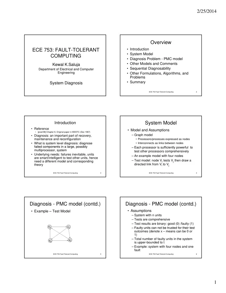
– Each processor is sufficiently powerful to test other processors comprehensively – An example model with four nodes – Test model: node Vi tests Vj then draw a directed link from Vi to Vj

Diagnosis - PMC model (contd.)

  • Example – Test Model

v2

v1

ECE 753 Fault Tolerant Computing 5

v4 v3

v2

v1

Diagnosis - PMC model (contd.)

  • Assumptions

– System with n units – Tests are comprehensive – Test results are binary: good (0) /faulty (1) Faulty units can not be trusted for their test

ECE 753 Fault Tolerant Computing 6

– Faulty units can not be trusted for their test

  • utcomes (denote x – means can be 0 or

1) – Total number of faulty units in the system is upper-bounded to t – Example: system with four nodes and one fault

slide-2
SLIDE 2

2/25/2014 2

Diagnosis - PMC model (contd.)

  • Example – Test outcomes
  • Assume V2 is faulty

v2

v1

1

ECE 753 Fault Tolerant Computing 7

v4 v3

v2

v1

x x

Diagnosis - PMC model (contd.)

  • One-step diagnosis

– Analysis problem – give a system with n units, all the interconnects, and the test

  • utcomes, identify the faulty units subject

to the constraint that no more than t units

ECE 753 Fault Tolerant Computing 8

in the system are faulty. – Design problem – design a system using fewest possible test links such that all the faulty units can be correctly identified in

  • ne-step knowing the outcomes of the

tests.

Diagnosis - PMC model (contd.)

  • One-step diagnosis - Example

– Consider all possible outcomes - fault a12 a23 a24 a31 a41 a43 none 0 0 0 0 0 0

ECE 753 Fault Tolerant Computing 9

V1 faulty x 0 0 1 1 0 V2 faulty 1 x x 0 0 0 V3 faulty 0 1 0 x 0 1 V4 faulty 0 0 1 0 x x each row is called Syndrome of the fault

Diagnosis - PMC model (contd.)

  • Observations
  • 1. Two possible syndromes associated with the

fault V1 and these are: 0 0 0 1 1 0

ECE 753 Fault Tolerant Computing 10

and 1 0 0 1 1 0

  • 2. No two faults have overlapping syndromes

Hence: we can correctly identify (diagnose) the faulty unit

Diagnosis - PMC model (contd.)

  • Consider two faulty units – say V1 and V2

possible syndrome x x x 1 1 0 implies

ECE 753 Fault Tolerant Computing 11

0 0 0 1 1 0 a possible

  • utcome

Therefore we can not determine if V1 alone or both V1 and V2 are faulty. Thus two faults in this system can not be diagnosed in one- step.

Diagnosis - PMC model (contd.)

  • Result: A system is one-step t-fault

diagnosable provided syndrome for each fault ( 0-fault, 1-fault, 2-faults, …, t-faults) are all distinct (non

ECE 753 Fault Tolerant Computing 12

) (

  • verlappling/non intersecting)
  • More results: -

but first one more assumption – no two units test each other

slide-3
SLIDE 3

2/25/2014 3

Diagnosis - PMC model (contd.)

  • Result 1:

For a system to be one-step t-fault diagnosable n ≧ 2t + 1

  • Result 2:

F b f l

ECE 753 Fault Tolerant Computing 13

For a system to be one-step t-fault diagnosable each unit must be tested by at least t other units

  • Theorem:

A system of n units in which no two units test each other is one step t-fault diagnosable if and only if each unit is tested by t other units.

Diagnosis - PMC model (contd.)

  • Design Problem – one-step t-fault

diagnosable system

  • Example – n = 7, t = 3

ECE 753 Fault Tolerant Computing 14

6 1 5 4 3 2

Diagnosis - PMC model (contd.)

  • Design Problem: Algorithm for a simple one-

step t-fault diagnosable with n ≧ 2t + 1

  • 1. Number the nodes from 0 to n-1
  • 2. draw a link from node i to i+1 (mod n),

ECE 753 Fault Tolerant Computing 15

( ), i+2 (mod n), … , i+t (mod n).

  • 3. System so designed is t-fault one-step

diagnosable.

Diagnosis - PMC model (contd.)

  • Systems in which some units test each
  • ther
  • One-step t-fault diagnosability

conditions are some what complex – See [prad:96]

ECE 753 Fault Tolerant Computing 16

[p ]

  • How does one check if a given system

is one-step t-fault diagnosable –

– Simple if no two units test each other – Some what complex if units test each other – There is a body of literature dealing with diagnosis algorithems

Other Models and Comments

Consider possible test outcomes when a unit Vi tests unit Vj – see the listing below

Vi Vj

  • utcomes

G G 0 0 0 0 0 0 0 0 1 1 1 1 1 1 1 1 G F 0 0 0 0 1 1 1 1 0 0 0 0 1 1 1 1

ECE 753 Fault Tolerant Computing 17

G F 0 0 0 0 1 1 1 1 0 0 0 0 1 1 1 1 F G 0 0 1 1 0 0 1 1 0 0 1 1 0 0 1 1 F F 0 1 0 1 0 1 0 1 0 1 0 1 0 1 0 1

0 1 2 3 4 5 6 7 8 9 10 11 12 13 14 15

Other Models/Comments(contd.)

– 4,5,6,7 PMC model – 8,9,10,11 PMC with complement encoding – 0,15 of little value t

ECE 753 Fault Tolerant Computing 18

– etc. – Some subset of PMC are more interesting – for example 5,7 – this implies that a unit being tested is always correctly identified, if faulty, independent

  • f the status of the testing unit. Many such

variations have been studied.

slide-4
SLIDE 4

2/25/2014 4

Other Models/Comments(contd.)

– Comparison based testing and diagnosis

  • A paper is in the IEEE Transactions of

Computers - February 2009 Issue

ECE 753 Fault Tolerant Computing 19

– Basically the model is built on PMC model

Sequential Diagnosability

  • Consider the following repair strategy

identify one or more faulty units repair them t t t i d ti till

ECE 753 Fault Tolerant Computing 20

test system again and continue till we know that there are no more faulty units –This is called sequential diagnosis

Sequential Diagnosability (contd.)

  • Assumptions

– Same as before:

  • System with n units
  • Tests are comprehensive

Test res lts are binar good (0) /fa lt (1)

ECE 753 Fault Tolerant Computing 21

  • Test results are binary: good (0) /faulty (1)
  • Faulty units can not be trusted for their test
  • utcomes (denote x – means can be 0 or 1)
  • Total number of faulty units in the system is

upper-bounded to t

Sequential Diagnosability (contd.)

  • Result 1:

For a system to be sequntially t-fault diagnosable

ECE 753 Fault Tolerant Computing 22

n ≧ 2t + 1 It is not necessary for every unit to be tested by t units

Sequential Diagnosability (contd.)

  • Example – n = 7, t = 3

6 1

ECE 753 Fault Tolerant Computing 23

5 4 3 2

Sequential Diagnosability (contd.)

  • It is easy to show that the example

system is sequentially 3-fault diagnosable

  • Above construction will require n+2t–1

ECE 753 Fault Tolerant Computing 24

q links

  • A better solution: A system with n+2t-2

links can be designed that is sequentially t-fault diagnosable

slide-5
SLIDE 5

2/25/2014 5

Sequential Diagnosability (contd.)

  • Proof:

– First construct the system – n nodes form a single loop, thus containing n links – Next choose some 2t-2 units and let these units test V0 unit

ECE 753 Fault Tolerant Computing 25

units test V0 unit – Now show that this system is sequentially t-fault diagnosable using the following three cases. Let n1 indicate the number of units which find V0 faulty. Similarly n0 indicate the units that find V0 not faulty. Clearly n1+ n0 = 2t-1

Sequential Diagnosability (contd.)

  • Proof:

– Case 1: n1 > t ---- V0 is faulty – Case 1: n1 < t ---- V0 is not faulty C 1 t f lt f it i t

ECE 753 Fault Tolerant Computing 26

– Case 1: n1 = t ---- a fault free unit exists that is not involved in testing V0

Sequential Diagnosability (contd.)

  • Sequential diagnosis – single loop system

– Example single loop system with n=5 – This is sequentially 2-fault diagnosable and can be demonstrated by constructing syndromes for different fault conditions. However, a system with

ECE 753 Fault Tolerant Computing 27

n=9 is NOT sequentially 4-fault diagnosable – General result: A single loop system is sequentially t-fault diagnosable if and only if n ≥ t + t2/4 + 2 for even t n ≥ t + [(t-1)(t+1)/4] + 2 for odd t

Other Formulations, Algorithms, and Problems

  • Generalization of sequential diagnosability

– Diagnose s faulty units at a time thus making a system t/s-sequentially diagnosable

  • Allow replacing up to t units – but not all units there

are replaced are faulty. In other words non faulty units can be replaced as long as all the faulty units

ECE 753 Fault Tolerant Computing 28

p g y are within the replaced units (t/t fault diagnosability) – An example in [prad:96] shows a system with 13 units, each unit is tested by 3 other units. Clearly such a system is only one-step 3-fault

  • diagnosable. But it is shown to be 5/5

diagnosable.

  • Even additional formulations exist

Other Formulations, Algorithms, and Problems

  • Diagnosis algorithms – Given a syndrome and

knowing that the system is t diagnosable, determine the set of faulty units – Possible solutions

Di ti h h t i ti l f l

ECE 753 Fault Tolerant Computing 29

  • Dictionary approach – some what impractical for large

systems

  • Algorithmic approach – based on graph models and

using solution to maximum matching problem

– Central v/s distributed algorithms

  • Diagnosis and reconfiguration in homogenous

and heterogeneous multicore systems

Summary

  • System diagnosis model
  • One-step t-fault diagnosis
  • Sequential diagnosis

ECE 753 Fault Tolerant Computing 30