orbivib std
play

OrbiVib Std Profibus DP interface 2 Digital inputs - PDF document

OrbiVib Std Profibus DP interface 2 Digital inputs with encoder function 2 Relay outputs 8 PT100 temperature inputs External Dual axis accelerometer


  1. OrbiVib Std • Profibus DP interface • • • • • • • 2 Digital inputs with encoder function • • 2 Relay outputs • • • 8 PT100 temperature inputs • • • • External Dual axis accelerometer • • • • • • • DIN-rail snap-on mounting • • Programmable configuration • • • Stand Alone security loop functionality • • • • Internal non-volatile vibration log data buffer • • • 
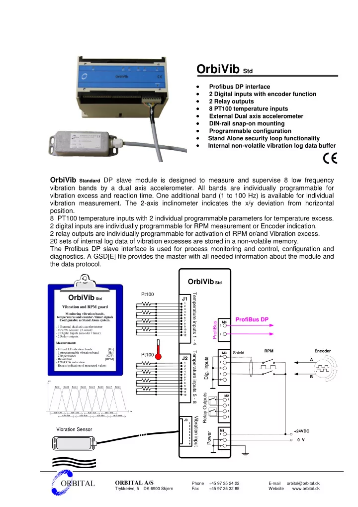
OrbiVib Standard DP slave module is designed to measure and supervise 8 low frequency vibration bands by a dual axis accelerometer. All bands are individually programmable for vibration excess and reaction time. One additional band (1 to 100 Hz) is available for individual vibration measurement. The 2-axis inclinometer indicates the x/y deviation from horizontal position. 8 PT100 temperature inputs with 2 individual programmable parameters for temperature excess. 2 digital inputs are individually programmable for RPM measurement or Encoder indication. 2 relay outputs are individually programmable for activation of RPM or/and Vibration excess. 20 sets of internal log data of vibration excesses are stored in a non-volatile memory. The Profibus DP slave interface is used for process monitoring and control, configuration and diagnostics. A GSD[E] file provides the master with all needed information about the module and the data protocol. OrbiVib Std Pt100 Temperature inputs 1 - 4 OrbiVib Std J1 1 2 Vibration and RPM guard 3 4 Monitoring vibration bands, 5 temperatures and counter / timer signals 6 ProfiBus DP Configurable as Stand Alone system. 7 ProfiBus M4 8 3 - 1 External dual axis accelerometer 9 10 - 8 Pt100 sensors. (3-wired) 11 - 2 Digital Inputs (encoder / timer). 8 12 - 2 Relay outputs. Measurement: - 8 fixed LF vibration bands [Hz] RPM Encoder Temperature inputs 5 - 8 - 1 programmable vibration band [Hz] Shield M3 Pt100 - Temperatures [C/F] 1 J2 Dig. Inputs - Revolution [RPM] A - CW/CCW indication 2 1 - Excess indication of measured values 2 3 3 4 4 5 B 6 5 7 2 m/s 8 9 Band 1 Band 2 Band 3 Band 4 Band 5 Band 6 Band 7 Band 8 10 11 Relay Outputs 12 M2 1 2 3 Hz 0.39 - 0.78 1.56 - 3.13 6.25 - 12.5 25.0 - 50.0 0.78 - 1.56 3.13 - 6.25 12.5 - 25.0 50.0 - 100.0 Vibration input 4 J3 1 2 Vibration Sensor 3 M1 +24VDC 4 Power 1 5 6 0 V 2 7 8 3 ORBITAL A/S Phone +45 97 35 24 22 E-mail orbital@orbital.dk Trykkerivej 5 DK 6900 Skjern Fax +45 97 35 32 85 Website www.orbital.dk

  2. OrbiVib lite • • Profibus DP interface • • • 2 Digital inputs with encoder function • • • • 2 Relay outputs • • • • • • • External Dual axis accelerometer • • DIN-rail snap-on mounting • • • Programmable configuration • • • • Stand Alone security loop functionality • • • • • • • Internal non-volatile vibration log data buffer OrbiVib lite DP slave module is designed to measure and supervise 8 low frequency vibration bands by a dual axis accelerometer. All bands are individually programmable for vibration excess and reaction time. One additional band is available for individual vibration measurement. (1 to 100 Hz) The 2-axis inclinometer indicates the x/y deviation from horizontal position. 2 digital inputs are individually programmable for RPM measurement or Encoder indication. 2 relay outputs are individually programmable for activation of RPM or/and Vibration excess. 20 sets of internal log data of vibration excesses are stored in a non-volatile memory. The Profibus DP slave interface is used for process monitoring and control, configuration and diagnostics. A GSD[E] file provides the master with all needed information about the module and the data protocol. OrbiVib _lite Vibration and RPM guard OrbiVib lite Monitoring of vibration bands, and counter / timer signals ProfiBus DP Configurable as Stand Alone system. ProfiBus M4 3 - 1 External dual axis accelerometer - 2 Digital Inputs (revolutions / encoder). 8 - 2 Relay outputs. Measurement: - 8 fixed LF vibration bands [Hz] RPM Encoder Shield - 1 programmable vibration band [Hz] M3 - Revolution [RPM] 1 Dig. Inputs - CW/CCW indication A - Excess indication of measured values 2 3 4 B 5 m/s 2 Band 1 Band 2 Band 3 Band 4 Band 5 Band 6 Band 7 Band 8 Relay Outputs M2 1 2 Security curcuit 3 Hz 0.39 - 0.78 1.56 - 3.13 6.25 - 12.5 25.0 - 50.0 0.78 - 1.56 3.13 - 6.25 12.5 - 25.0 50.0 - 100.0 Vibration input 4 J3 1 2 Vibration Sensor 3 M1 +24VDC 4 Power 5 1 6 0 V 7 2 8 3 ORBITAL A/S Phone +45 97 35 24 22 E-mail orbital@orbital.dk Trykkerivej 5 DK 6900 Skjern Fax +45 97 35 32 85 Website www.orbital.dk

  3. OrbiVib 232 • RS232 Interface / Modbus protocol • • • • • • • 2 Digital inputs with RPM / Encoder function • • 2 Relay outputs • • • External Dual axis accelerometer • • • • DIN-rail snap-on mounting • • • • • • • Programmable configuration • • Stand Alone security loop functionality • • • Internal non-volatile vibration log data buffer • • • OrbiVib 232 module is designed to measure and supervise 8 low frequency vibration bands by a dual axis accelerometer. All bands are individually programmable for vibration excess and reaction time. One additional band is available for individual vibration measurement. (1 to 100 Hz) The 2-axis inclinometer indicates the x/y deviation from horizontal position. 2 digital inputs are individually programmable for RPM measurement or Encoder indication. 2 relay outputs are individually programmable for activating a security circuit on RPM or/and Vibration excesses. 50 sets of internal log data of vibration excesses are stored in a non-volatile memory. The RS232 interface supports Modbus protocol and is used for process monitoring, control and configuration. OrbiVib 232 OrbiVib 232 Vibration and RPM guard Monitoring of vibration bands, and M4 counter / timer signals Modbus protocol 1 TX - Stand Alone system - 2 RX 2 3 3 4 2 - 1 External dual axis accelerometer Gnd S 5 - 2 Digital Inputs (revolutions / encoder). PC R 6 - 2 Relay outputs. 7 CTS Measurement: 8 RTS 9 - 8 fixed LF vibration bands [Hz] - 1 programmable vibration band [Hz] - Revolution [RPM] RPM Encoder M3 Shield - CW/CCW indication - Excess indication of measured values 1 s A t u 2 p n 3 I . g 4 i B D 5 m/s 2 Band 1 Band 2 Band 3 Band 4 Band 5 Band 6 Band 7 Band 8 Relay Outputs M2 1 Security 2 curcuit 3 Hz 0.39 - 0.78 1.56 - 3.13 6.25 - 12.5 25.0 - 50.0 0.78 - 1.56 3.13 - 6.25 12.5 - 25.0 50.0 - 100.0 Vibration input 4 J3 1 2 Vibration Sensor 3 M1 +24VDC 4 r e 5 1 w 6 0 V o 2 7 P 8 3 ORBITAL A/S Phone +45 97 35 24 22 E-mail orbital@orbital.dk Trykkerivej 5 DK 6900 Skjern Fax +45 97 35 32 85 Website www.orbital.dk

  4. Electrical specifications OrbiVib std Conditions Min. Typ. Max. Units Parameter Power supply Supply voltage 19,0 24,0 30,0 Vdc Power consumption 10,0 W 24,0 Vdc ± 10% supply voltage Relay outputs Switching voltage 380 / 125 Vac / Vdc Resistive load (cos ϕ = 1) Switching current 5 / 5 Aac / Adc Switching capacity 1250 / 150 VA / W Scan cycle 100 msec Digital / Counter inputs Input impedance 4400 Ω Input voltage Continuous 24,0 V ± 60,0 Low level input 8,0 V High level input 16,0 V Input frequency Duty cycle 50% 50,0 Hz Profibus Baud rate 9600 12M Baud Pt 100 inputs Range -50 / -58 200 / 392 °C / °F Linearity error °C ± 0,1 Accuracy 0,3 °C Sensor connections Output supply voltage 10,0 14,0 24,0 Vdc Output supply current 75,0 mA Accelerometer Cable length Sensor to module 20 m Peak range 0° / 90° level X and/or Y axis 0°/ 90° to earth 10,0 / 4,0 15,0 / 6,0 m/s² Module Counter/Encoder Power Profibus Digital Outputs address input supply Mechanical dimensions: DC DC CPU 150 mm I/O 110 mm External Vibration 8 Pt 100 inputs Sensor 75 mm

  5. Electrical specifications OrbiVib lite Parameter Conditions Min. Typ. Max. Units Power supply Supply voltage 19,0 24,0 30,0 Vdc Power consumption 24,0 Vdc ± 10% supply voltage 10,0 W Relay outputs Switching voltage 380 / 125 Vac / Vdc Resistive load (cos ϕ = 1) Switching current 5 / 5 Aac / Adc Switching capacity 1250 / 150 VA / W Scan cycle 100 msec Digital / Counter inputs Input impedance 4400 Ω Input voltage Continuous 24,0 V ± 60,0 Low level input 8,0 V High level input 16,0 V Input frequency Duty cycle 50% 50,0 Hz Profibus Baud rate 9600 12M Baud Sensor connections Output supply voltage 10,0 14,0 24,0 Vdc Output supply current 75,0 mA Sensor Cable length 20 m Peak range 0° / 90° level X and/or Y axis 0°/ 90° to earth 10,0 / 4,0 15,0 / 6,0 m/s² External Vibration Sensor Mechanical dimensions: Module Power Profibus address supply DC ACC DC . 100 mm CPU RPM 110 mm 75 mm Counter/Encoder Digital Outputs input

Download Presentation
Download Policy: The content available on the website is offered to you 'AS IS' for your personal information and use only. It cannot be commercialized, licensed, or distributed on other websites without prior consent from the author. To download a presentation, simply click this link. If you encounter any difficulties during the download process, it's possible that the publisher has removed the file from their server.

Recommend


More recommend