ON FIBER DIRECTION AND POROSITY CONTENT USING ULTRASONIC PITCH-CATCH - - PDF document

on fiber direction and porosity content using ultrasonic
SMART_READER_LITE
LIVE PREVIEW

ON FIBER DIRECTION AND POROSITY CONTENT USING ULTRASONIC PITCH-CATCH - - PDF document

18 TH INTERNATIONAL CONFERENCE ON COMPOSITE MATERIALS ON FIBER DIRECTION AND POROSITY CONTENT USING ULTRASONIC PITCH-CATCH TECHNIQUE IN CFRP COMPOSITE SOLID LAMINATES K.H. Im 1* , Y. H. Hwang 1 , C. H. Song 1 , T. H. Kim 1 , J. W. Park 2 , D. K.


slide-1
SLIDE 1

18TH INTERNATIONAL CONFERENCE ON COMPOSITE MATERIALS

1 Introduction Composite materials of engineering materials [1] are attractive for a wide range of applications. The importance of carbon-fiber reinforced plastics (CFRP) in both space and civil aircraft have been generally recognized, and CFRP composite laminates are widely used. So, CFRPs are a material class for which nondestructive material property characterization is as important as flaw detection [2]. Fiber reinforced composite laminates often possess strong in-plane elastic anisotropy attributable to the specific fiber orientation and layup sequence]. However one of important factors is the ply-layup

  • rientation which can influence the CFRP composite
  • performance. This greatly affects its properties in the

composite laminate. It is very necessary to detect flaws and defects in the CFRP composite solid laminates due to the flaws of FRP composite laminates affecting the properties of the laminate, including stiffness and strength. It is well known that, in composite laminates, the backscattered time- domain signal can exhibit significant fluctuation with transducer position on the sample. The sources

  • f the backscattered signals in solid composite

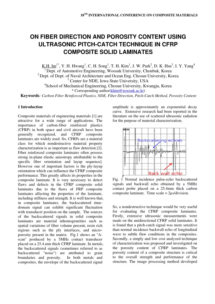
laminates are material inhomogeneities such as spatial variations of fiber volume percent, resin rich regions such as the ply interfaces, and micro- porosity present in the matrix. Fig.1 shows an "A- scan" produced by a 5MHz contact transducer placed on a 25.4.mm thick CFRP laminate. In metals, the backscattered signals (sometimes referred to as backscattered "noise") are attributed to grain boundaries and porosity. In both metals and composites, the envelope of the backscattered signal amplitude is approximately an exponential decay

  • curve. Extensive research had been reported in the

literature on the use of scattered ultrasonic radiation for the purpose of material characterization.

  • Fig. 1 Normal incidence pulse-echo backscattered

signals and backwall echo obtained by a 5MHz contact probe placed on a 25.4mm thick carbon composite laminate. Time scale = 2µs/division. So, a nondestructive technique would be very useful for evaluating the CFRP composite laminates. Firstly, extensive ultrasonic measurements were made on the unidirectional CFRP solid laminates. It is found that a pitch-catch signal was more sensitive than normal incidence backwall echo of longitudinal wave to subtle flaw conditions in the composites. Secondly, a simply and low cost analyzed technique

  • f characterization was proposed and investigated on

the porosity content of CFRP laminates. The porosity content of a composite structure is critical to the overall strength and performance of the

  • structure. The image processing method developed

ON FIBER DIRECTION AND POROSITY CONTENT USING ULTRASONIC PITCH-CATCH TECHNIQUE IN CFRP COMPOSITE SOLID LAMINATES

K.H. Im1*, Y. H. Hwang1, C. H. Song1, T. H. Kim1, J. W. Park2, D. K. Hsu3, I. Y. Yang4

1 Dept. of Automotive Engineering, Woosuk University, Chonbuk, Korea 2 Dept. of Dept. of Naval Architecture and Ocean Eng. Chosun University, Korea 3 Center for NDE, Iowa State University, USA 4School of Mechanical Engineering, Chosun University, Kwangju, Korea

* Corresponding author(khim@woosuk.ac.kr)

Keywords: Carbon Fiber Reinforced Plastics, NDE, Fiber Direction, Pitch-Catch Method, Porosity Content

slide-2
SLIDE 2

utilizes a free software package to process micrograph images of the test sample. The results from the image processing method are compared with existing data. Also, it is confirmed that the pitch-catch ultrasonic signal was corresponding with simulated results assuming in unidirectional CFRP composites. 2 Experimental System 2.1 Specimen configuration Test specimens were prepared with dimensions, 100mm × 100mm × 7.0 and 23.3mm (width × length × thickness). Their lay-ups are [0]56 and [0]180. Also, as for porosity specimens, two types of specimens were used in this experimentation. Their lay-up, stacked with 16 plies, is as A [45/-45/0/90/45/- 45/0/90]s and B [0/-45/45/90]2s respectively. The pitch-catch ultrasonic C-scans were conducted in an immersion tank using a SONIX scanning system. A pair of 2.25MHz Rayleigh transducers were aligned perpendicular to the CFRP composites and driven by a Panametrics 5052 pulser/receiver. To reduce the effect of water absorption in sample, we have put a small amount of couplant on the sample surface and used a lower frequency transducer (2.25MHz). The miniature, potted angle beam transducers have external dimensions of 18 x 16 x 8.4 mm. According to the transducer manufacturer [3] the angle of incidence in the plastic wedge is 64 degrees for the Rayleigh wave transducer (for steel) and the speed

  • f sound in the wedge is 2.79 mm/µs.

The pitch-catch ultrasonic C-scans were conducted in an immersion tank using a SONIX scanning

  • system. A 2.25MHz, 6.35mm diameter, focused

transducers and Rayleigh wave transducer were aligned perpendicular to the disk and driven by a Panametrics 5052 pulser/receiver. Schematic for experimental setup was shown in Fig. 2(a) and Fig. 2(b) shows a beam profile of Rayleigh wave transducers. Table 1 shows the porosity levels of specimens A and B. The porosity data were given by the supplier as a reference.

(a)One-sided pitch-catch (b)Two-sided pitch-catch

Fig.2. Pitch-catch measurement on composite laminate using miniature potted angle beam transducers Table 1. Porosity specimens

No.

Specimen name.

1 2 3 4 5 6 A 0.2 1.14 1.89 2.04 6.51 6.53 B 0.34 1.25 2.84 3.87 4.05 5.33

2.2 Image processing The CFRP composite laminates were mounted using the Epoxicure metallurgical mounting system. The mounted samples were polished through 0.3 micron

  • abrasives. The polished mounts were then placed on

an inverted stage microscope where digital micrographs were captured. At this magnification the porosity was readily visible while still being able to see a large area of the sample. This elimination is done by thresholding and filtering. Thresholding creates a binary image by turning every pixel with a value above the threshold white, and below black. The filter’s smoothing action creates a grayscale image from the binary image. ImageTool, the open source software from UTHSCSA (2005) was used to process the images from their original state to a binary version where black and white pixels could be counted to obtain an area of porosity

  • measurement. It can be seen that the image still

contains some black pixels that are not actual porosity when compared to the original, Fig. 3b. The filtering step is applied to help eliminate the black pixels that are not actual porosity. image, Fig. 2f. The human factors were evaluated by comparing the image processing results obtained using the manual threshold values chosen by four individuals. The Smooth filter was used and could be found under the processing menu. The image is now ready to be thresholded again following the same procedure described earlier, Fig. 3c. This process was repeated,

  • Figs. 3d-3e, until the operator satisfied that the final
slide-3
SLIDE 3

3 PAPER TITLE

binary image represented only the porosity present in the original

  • Fig. 3 The original image (a) through the final

processed image (f) as captured from the automated process of ImageTool of a specimen. Images (b, d, f) are after thresholding while images (c and e) are after filtering steps. 3 Results and Discussion 3.1 NDE characterization of solid composites In any one-sided, one transducer measurement, whether it is normal incidence pulse-echo or oblique incidence backscattering, there is a "dead zone" at the beginning of the time-domain A-scan due to transducer ring-down and the recovery of a saturated

  • receiver. A simple advantage of double-ended

measurement using two transducers, either normal incidence through transmission or one-sided pitch- catch, is that it is free of the dead zone. It should be noted that when wedged angle beam transducers are used in pitch-catch, there is a time delay for the propagation through the wedges. In the course of applying pitch-catch method for the nondestructive evaluation of composite solid laminates, it was

  • bserved that, in contrast to the fluctuating pulse-

echo signal, the pitch-catch signal in composites was remarkably constant with respect to the position on the sample. Moreover, the baseline both before and after the arrival of the pitch-catch signal was distinctly noise free. Figure 4 shows this contrast at two random locations on a 19.5 and 25.4 mm thick unidirectional CFRP laminate. The pitch-catch signals were obtained using a pair of miniature potted angle beam transducers designed for producing Rayleigh waves in steel. The probes were mounted in a holder, in a nose-to- nose fashion, and the wave pitch-catch direction was normal to the fibers. The fact that backscattered signals in normal incidence pulse-echo fluctuate with transducer position whereas the pitch-catch signal remains largely constant can at least be partly attributed to the fact that piezoelectric transducers are phase sensitive devices and are therefore subject to constructive or destructive interference between received signals. In a pulse-echo situation, the backscattered signals returned to the transducer by the various scatters in the sample can interfere with each other, leading to considerable fluctuation as the transducer moves on the surface. In a pitch-catch situation, the specularly scattered signals arrive at the receiver more or less in phase due to the time window effect described above. As a result, there is much less phase enhancement or cancellation effects

  • n the signal.
  • Fig. 4 A comparison of pulse-echo and pitch-catch

signals obtained at two random locations on a 19.5 and 25.4 mm thick CFRP solid laminate Backscattered signal acquired with a 2.25 and 5 MHz normal incidence contact transducer.

slide-4
SLIDE 4
  • Fig. 5 shows three peaks between time-of-flight and

amplitude when one-sided pitch-catch experiments have been carried out in a manner of head-to-head contact mode. To understand the mode of the waves, the angle of refraction, and the propagation speed of the pitch-catch signal, experiments are performed in unidirectional CFRP laminates.

  • Fig. 5 Time-of-flight and amplitude of received

signal normal to fiber (a) (b)

  • Fig. 6 Second signal amplitude of pitch-catch signal

for one-sided beam profile prediction for Relation between probe distance and TOF (b) Beam profile path One type for beam path can be expected in unidirectional composite laminates. It is assumed that S-L wave (L; longitudinal and S: shear) is propagating normal to fiber in a 25.4 mm thick unidirectional CFRP laminate. Figure 6 shows signal amplitude of pitch-catch signal in one-sided beam profile prediction using unidirectional CFRP laminates ( 25.4 mm in thickness) normal to fiber. At that time, three peak-to-peak amplitudes were acquired when two Rayleigh wave transducers touched with head-to-head position at the distance between probes. As shown in Fig.6 (a), graph was plotted between signal amplitude and distance of

  • probes. The first peak decreased as probe distance

increased and the second & third peaks go up and down as the probe distance increased. Also, Fig.6 (b) shows the beam profile prediction. A linear relationship was observed and experimental and calculated results were well agreed. To understand the mode of the waves, the angle of refraction, and the propagation speed of the pitch-catch signal, experiments are performed in unidirectional CFRP

  • laminates. Fig.6(b) shows one type for beam path in

unidirectional composite laminates. It is assumed that S-L wave (L; longitudinal and S: shear) is propagating normal to fiber in a 25.4 mm thick unidirectional CFRP laminate. Let us assume the wave propagations is going into the sample from the

  • testing. Firstly, longitudinal wave from Rayleigh

wave transducer is coming out; in the mid area, this wave is supposed to change to the Rayleigh wave. However, the wave goes into the unidirectional CFRP composite laminates and those are reflected to the direction of receiver of Rayleigh wave

  • transducers. So, it is expected that one-sided

measurement could be possibly to obtain the ultrasonic signal at the arbitrary point which would contain almost exclusively the status information in the ply. 3.2 Correlation with porosity content In the study of correlation between pitch-catch signal amplitude and porosity volume fraction, two sets of CFRP specimens were used: quasi-isotropic laminates, and woven laminates. The woven laminates have a 0/±45/90 layup. Each set includes specimens containing nominally 0% to 6% porosity. The laboratory samples were processed first to evaluate the effectiveness of the image processing

  • method. Specimen B has a very linear distribution
  • f porosity compared to the A specimen group;

however, specimen A shows discrepancy of porosity to some degree according to ultrasonic inspection results and the Reference data. This combined with the morphology encountered in woven lay ups can explain the very good correlation between the image processing method. Also, the Reference data were shown in Fig. 7. Specimen Nos 4, 5, and 6 of Fig. 7 (a) and (b) have a difference of measured porosity level according to ultrasonic

  • inspection. Since only one plane of the sample is

being inspected at a time by the image processing

slide-5
SLIDE 5

5 PAPER TITLE

method it is easy to see that there can be variations in the porosity content from one plane to another.

  • Fig. 8 shows the C-scan variation images with using

pitch- (a) Specimen A (b) Specimen B

  • Fig. 7 The comparison between the porosity levels
  • btained from the image processing method and the

Reference data on specimen A and B.

  • Fig. 8 Variation images between pitch-catch signal

amplitude and porosity level in the specimen A (unidirectional laminates) catch contact mode and pulse-echo amplitude techniques respectively. Variation of pitch-catch images agreed well with increasing of porosity level in CFRP composites. It seems that the pitch-catch images are influenced by the porosity level such as those C-scan images as

  • expected. Accordingly, it is found that there exists a

possibility to map out C-scan images with the porosity level using a one-sided pitch-catch mode. Therefore, the one-sided and pitch-catch technique was found to have certain sensitivity advantages in addition to the fact that it does not require a backwall echo as well. In detecting subtle defects, such as porosity volume, the pitch-catch signal was found to be reasonably effective. The presence of porosity in CFRP is expected to increase the amount

  • f scattering; however, porosity will also greatly

increase the attenuation of the propagating ultrasonic beam leading to the pitch-catch scattering zone and also from the scattering zone to the receiving

  • transducer. Judging from the fact that the pitch-

catch signal amplitude decreased precipitously with increasing porosity, the attenuation effect seems to be the dominating factor. In addition, it should also be recognized that, when testing a thin plate with the pitch-catch method, the detailed wave propagation parameters are complex to analyze. The pitch-catch and GenScan [2] combination was used to map out embedded flaws and impact damages in a variety of glass fiber reinforced composite laminates and carbon composites. Figure 9 shows the pitch-catch C-scan image of an impact damage in a 24-ply woven glass composite laminate caused by a drop weight kinetic energy of 16.6J. The damage was detectable by the pitch-catch probe placed on either the impacted side or the back side. The outer dimension of the circular impact damage was approximately 31.75mm diameter. Using the pair of potted angle beam Rayleigh transducers and the GenScan setup, a C-scan image was generated, as shown in Fig. 9. The footprint of the pair of Rayleigh wave transducers was about 38.1 x 6.35mm. The long dimension is in the horizontal direction, which was also the scan direction. Figure 9 shows two pixel sizes: the scan was first made with 6.35mm pixels and then refined around the flaw to obtain a finer definition of the flaw shape. Light gray represents high signal amplitude, dark gray represents low signal amplitude, and the boundary area was not scanned.

  • Fig. 9 Pitch-catch scan image of an impact site on a

24-ply woven glass composite laminate. The image of the circular 31.75mm diameter impact damage in the GFRP laminate appears flattened and slightly oversized in the horizontal direction. This distortion was caused by the fact that the footprint of the pitch-catch transducers was a rectangle and its

slide-6
SLIDE 6

long dimension was slightly greater than the flaw

  • size. Images like the one shown in Fig. 9 can be

generated manually very quickly using the pitch- catch and GenScan combination. Even though the wave mode(s) produced by the pitch-catch probe in the relatively thin glass composite laminate cannot be easily determined, the dark region (low signal amplitude) was a reasonably good representation of the impact damage in the laminate in terms of size and shape. 3.3 Simulation for pitch-catch method Simulation was performed with the numerical Wave-2000 Code (Cyber Logic. Co. Ltd.). The unidirectional CFRP composite laminates as shown in Figure 10 was represented in the numerical model, including fibers and resin. Approximately 0.5mm in diameter for fibers are included in the model which was exaggerated compared with real fibers. Fig.10 Beam path simulations of pitch-catch Rayleigh wave in unidirectional CFRP composites. However the trend of wave propagation could be

  • bserved in this model. The relevant parameters

used for the unidirectional CFRP composite laminates are as follow; 1) density is 1.83x10³(kg/m3), Young’s modulus is 240 GPa for fibers and 2) density is 1.24x10³(kg/m3), Young’s modulus is 3.6 GPa for resin, which volume content is 33% Wt.. Sound velocity of the longitudinal wave cL=5583m/s, sound velocity of the shear wave cS=3179m/s and the Rayleigh wave speed cR=2982m/s for the Rayleigh wave transducer. The frequency of transducer is 2.25 MHz. In pulse-echo measurements, the backscattered signals come from all along the propagation path. As a result, the signal amplitude diminishes with propagation time or depth. In pitch-catch measurements, the signals come mainly from the region where the transmitting beam intersects the receiving beam (the "scattering zone"). Therefore, the scattered signals are received by the receiving

  • transducer. Signals scattered from the transmitting

beam would arrive at the receiving transducer at angles from the angle of Snell’s law. Such scattered signals with an early or late arrival time would arrive the receiving piezoceramic element at a very low amplitude level. So it is found that there exists a good trend in the wave propagation between experimental and calculated results. Therefore those results seem to show a qualitative agreement for the experimental and calculated solutions. 4 Conclusions In our aim to develop ultrasonic inspection techniques for thick composite solid laminates on the primary structures of the new generation of airplanes, we investigated the pitch-catch configuration for cases where the backwall echo is not available. The pitch-catch configuration was investigated for cases under no backwall echo. Therefore, it is found that pitch-catch was effective in analyzing ultrasonic behavior and imaging in unidirectional CFRP laminates. The percent porosity results from the image processing method correlate to some degree with the reference data for the CFRP laminates, and this method is viable for determining the porosity content. Acknowledgements This work was supported by Chosun University, Gwangju, Korea made in the 2009 academic year. References

[1] K.H. Im, S. K. Kim, I. Y. Yang “Impact

Damage and Hygrothermal Effects on Fatigue Bending Strength of Orthotropy Composite Laminates”, KSME International Journal, Vol 13, No. 7, pp.524-535,1999.

[2] D. J. Barnard and D. K. Hsu, "Development of

practical NDE methods for composite aircraft structures," Review of Progress in Quantitative NDE, Vol. 25, pp. 1019-1026,2005.

[3] Olympus

NDT, Inc., Vendor

  • f

Staveley/QualCorp miniature potted angle beam transducers, 2010.