Microprocessors & Interfacing Data Representation Number - - PowerPoint PPT Presentation

microprocessors interfacing
SMART_READER_LITE
LIVE PREVIEW

Microprocessors & Interfacing Data Representation Number - - PowerPoint PPT Presentation

Lecture Overview Microprocessor Hardware Structures Microprocessors & Interfacing Data Representation Number representation Instruction Set Basics of Computing with Microprocessor Systems Lecturer : Dr. Annie Guo S2,


slide-1
SLIDE 1

S2, 2008 COMP9032 Week1 1

Microprocessors & Interfacing

Basics of Computing with Microprocessor Systems

Lecturer : Dr. Annie Guo

S2, 2008 COMP9032 Week1 2

Lecture Overview

  • Microprocessor Hardware Structures
  • Data Representation

– Number representation

  • Instruction Set

S2, 2008 COMP9032 Week1 3

CPU datapath

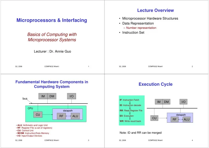
Fundamental Hardware Components in Computing System

  • ALU: Arithmetic and Logic Unit
  • RF: Register File (a set of registers)
  • CU: Control Unit
  • IM/DM: Instruction/Data Memory
  • I/O: Input/Output Devices

ALU RF CU IM DM I/O bus

S2, 2008 COMP9032 Week1 4

Execution Cycle

IF: Instruction Fetch ID: Instruction decode RR: Read Register File EX: Execution WR: Write result back

datapath

ALU RF CU IM DM I/O Note: ID and RR can be merged

slide-2
SLIDE 2

S2, 2008 COMP9032 Week1 5

Microprocessors

  • A microprocessor is the

datapath and control unit

  • n a single chip.
  • If a microprocessor, its

associated support circuitry, memory and peripheral I/O components are implemented on a single chip, it is a microcontroller.

– We use AVR microcontroller as the example in our course study

S2, 2008 COMP9032 Week1 6

Data Representation

  • For digital microprocessor system being able

to compute and process data, the data must be properly represented

– How to represent numbers for calculation? – How to represent characters, symbols and other physical values for processing?

  • Will be covered later

S2, 2008 COMP9032 Week1 7

Number Representation

  • Any number can be represented in the form
  • f

r a base radix, : r r a ... r a a r a ... r a r a ) ...a a . a ...a a (a

i m m 1 1

  • 1

1 n 1 n n n r m

  • 1
  • 1

1 n n

< < < < ≤ ≤ ≤ ≤ × × × × + + + + + + + + × × × × + + + + + + + + × × × × + + + + + + + + × × × × + + + + × × × × = = = =

− − − − − − − − − − − − − − − − − − − − − − − −

S2, 2008 COMP9032 Week1 8

Decimal

  • Example

– The place values, from right to left, are 1, 10, 100, 1000 – The base or radix is 10 – All digits must be less than the base, namely, 0~9

7 10 9 10 5 10 3 (3597)

2 3 10

+ + + + × × × × + + + + × × × × + + + + × × × × = = = =

slide-3
SLIDE 3

S2, 2008 COMP9032 Week1 9

Binary

  • Example

– The place values, from right to left, are 1, 2, 4, 8 – The base or radix is 2 – All digits must be less than the base, namely, 0~1

1 2 1 2 2 1 (1011)

2 32

+ + + + × × × × + + + + × × × × + + + + × × × × = = = =

S2, 2008 COMP9032 Week1 10

Hexadecimal

  • Example

– The place values, from right to left, are 1, 16, 162, 163 – The base or radix is 16 – All digits must be less than the base, namely, 0~9,A,B,C,D,E,F

11 16 4 16 2 16 15 B 16 4 16 2 16 F (F24B)

2 3 2 3 16

+ + + + × × × × + + + + × × × × + + + + × × × × = = = = + + + + × × × × + + + + × × × × + + + + × × × × = = = =

S2, 2008 COMP9032 Week1 11

Which numbers to use?

  • Binary numbers

– Used by digital systems

  • Because digital devices can easily produce high or low

level voltages, which can represent 1 or 0.

  • Decimals

– Used by humans

  • Hexadecimals or sometimes octal numbers

– For neat binary representation – For easy number conversion between binary and decimal

  • Please see the additional material provided

S2, 2008 COMP9032 Week1 12

Binary Arithmetic Operations

  • Similar to decimal calculations
  • Examples of addition and multiplication are

given in the next two slides.

slide-4
SLIDE 4

S2, 2008 COMP9032 Week1 13

Binary Additions

  • Example:

– Addition of two 4-bit unsigned binary numbers. How many bits are required for holding the result? 1001+0110 = (__________)

S2, 2008 COMP9032 Week1 14

Binary Multiplications

  • Example:

– Multiplication of two 4-bit unsigned binary

  • numbers. How many bits are required for holding

the result? 1001*0110 = (____________________)

S2, 2008 COMP9032 Week1 15

Negative Numbers & Subtraction

  • Subtraction can be defined as addition of the additive

inverse:

a – b = a + (-b)

  • To eliminate subtraction in binary arithmetic, we can

represent –b by two’s complement of b.

  • In n-bit binary arithmetic, 2’s complement of b is

b* = 2n – b

– (b*)* = b – The MSB (Most Significant Bit) of a 2’s complement number is the sign bit

  • For example, for a 4-bit 2’s complement system,
  • (1001) -7,

(0111) 7

S2, 2008 COMP9032 Week1 16

Examples

2’s complement numbers

  • Represent the following decimal numbers using 8-

bit 2’s complement format

(a) 7 (b) 127 (c) -12

  • Can all the above numbers be represented by 4

bits?

  • An n-bit binary number can be interpreted in two

different ways: signed or unsigned. What value does the 4-bit number, 1011, represent?

(a) if it is a signed number, or (b) if it is an unsigned number

slide-5
SLIDE 5

S2, 2008 COMP9032 Week1 17

Examples

4-bit 2’s-complement additions/subtractions

(1) 0101 - 0010 (5 - 2):

0101 + 1110 (= 0010*) = 10011

(2) 0010 - 0101 (2 - 5):

0010 + 1011 (= 0101*) = 1101 (= 0011*). Result means -3.

(3) -0101 - 0010 (-5 - 2):

1011 (= 0101*) + 1110 (= 0010*) = 11001 Result is 0111* (how?) and means -7.

(4) 0101 + 0010 (5 + 2):

This is trivial, as no conversions are

  • required. The result is 0111 (= 7).

S2, 2008 COMP9032 Week1 18

Overflow in Two’s-Complement

  • Assume a, b are positive numbers in an n-bit

2’s complement systems,

– For a+b

  • If a+b > 2n-1 - 1, then a+b represents a negative number;

this is positive overflow.

– For -a-b

  • If –a-b < 2n-1, then –a-b results in a positive number; this

is negative overflow.

S2, 2008 COMP9032 Week1 19

Positive Overflow Detection

Addition of 4-bit positive numbers without

  • verflow looks like this:

0xxx + 0xxx = 0xxx . The “carry in” to the MSB must have been 0, and the carry out is 0. Positive overflow looks like this: 0xxx + 0xxx = 1xxx . The “carry in” to the MSB must have been 1, but the carry out is 0. Overflow occurs when carry in carry out. ≠

S2, 2008 COMP9032 Week1 20

Negative Overflow Detection

Addition of negative twos- complement numbers without overflow: 1xxx + 1xxx = 11xxx . The carry in to the MSB must have been 1 (otherwise the sum bit would be 0), and the carry out is 1. Negative overflow: 1xxx + 1xxx = 10xxx . The carry in to the MSB must have been 0, but the carry out is 1. So negative overflow, like positive, occurs when carry in carry out. ≠

slide-6
SLIDE 6

S2, 2008 COMP9032 Week1 21

Overflow Detection

  • For n-bit 2’s complement systems, condition
  • f overflow for both addition and substraction:

– The MSB has a carry-in different from the carry-

  • ut

S2, 2008 COMP9032 Week1 22

Examples

  • 1. Do the following calculations, where all

numbers are 4-bit 2’s complement numbers. Check whether there is any overflow.

(a) 1000-0001 (b) 1000+0101 (c) 0101+0110

S2, 2008 COMP9032 Week1 23

Microprocessor Applications

  • A microprocessor application system can be

abstracted in a three-level architecture

– ISA is the interface between hardware and software

Software Hardware Hardware C program ISA level ISA program executed by hardware FORTRAN 90 program FORTRAN 90 program compiled to ISA program C program compiled to ISA program program Assembly S2, 2008 COMP9032 Week1 24

Instruction Set

  • Instruction set provides the vocabulary and grammar

for programmer/software to communicate with the hardware machine.

  • It is machine oriented

– Different machine, different instruction set

  • For example

– 68K has more comprehensive instruction set than ARM machine

– Same operation, could be written differently in different machines

  • AVR

– Addition: add r2, r1 ;r2 r2+r1 – Branching: breq 6 ;branch if equal condition is true – Load: ldi r30, $F0 ;r30 Mem[F0]

  • 68K:

– Addition: add d1,d2 ;d2 d2+d1 – Branching: breq 6 ;branch if equal condition is true – Load: mov #1234, D3 ;d2 1234

slide-7
SLIDE 7

S2, 2008 COMP9032 Week1 25

Instructions

  • Instructions can be written in two languages

– Machine language

  • Made of binary digits
  • Used by machines

– Assembly language

  • A textual representation of machine language
  • Easier to understand than machine language
  • Used by human beings.

S2, 2008 COMP9032 Week1 26

Machine Code vs. Assembly Code

  • Basically, there is a one-to-one mapping between the

machine code and assembly code

– Example (Atmel AVR instruction):

For increment register 16:

  • 1001010100000011

(machine code)

  • inc r16

(assembly language)

  • Assembly language also includes directives

– Instructions to the assembler

  • The assembler is a program to translate assembly code into

machine code.

– Example:

  • .def temp = r16
  • .include “mega64def.inc”

S2, 2008 COMP9032 Week1 27

Example (AVR instruction)

  • Subtraction with carry

– Syntax: sbc Rd, Rr – Operation: Rd ← Rd – Rr – C – Rd: Destination register. 0 ≤ d ≤ 31 – Rr: Source register. 0 ≤ r ≤ 31, C: Carry

  • Instruction format

0 0 0 0 1 0 r d r r r r d d d d 15

S2, 2008 COMP9032 Week1 28

Instruction Set Architecture (ISA)

  • ISA specifies all aspects of a computer

architecture visible to a programmer

– Instructions (just mentioned) – Native data types – Registers – Memory models – Addressing modes

slide-8
SLIDE 8

S2, 2008 COMP9032 Week1 29

Native Data Types

  • Different machines support different data

types in hardware

  • e.g. Pentium II:
  • e.g. Atmel AVR:
  • Floating point
  • BCD integer
  • Unsigned integer
  • Signed integer

128 bits 64 bits 32 bits 16 bits 8 bits Data Type Floating point BCD integer

  • Unsigned integer
  • Signed integer

128 bits 64 bits 32 bits 16 bits 8 bits Data Type S2, 2008 COMP9032 Week1 30

Registers

  • Two types

– General purpose – Special purpose

  • e.g.

– Program Counter (PC) – Status Register – Stack pointer (SP) – Input/Output Registers

– Stack pointer and Input/Output Registers will be discussed in detail later.

S2, 2008 COMP9032 Week1 31

General Purpose Registers

  • A set of registers in the machine

– Used for storing temporary data/results – For example

  • In (68K) instruction add d3, d5, operands are stored in general

registers d3 and d5, and the result is stored in d5.

  • Can be structured differently in different machines

– For example

  • Separated general purpose registers for data and address

– 68K

  • Different number of registers and different size of registers

– 32 32-bit registers in MIPS – 16 32-bit registers in ARM

S2, 2008 COMP9032 Week1 32

Program Counter (PC)

  • Special register

– For storing the memory address of currently executed instruction

  • Can be of different size

– E.g. 16 bit, 32 bit

  • Can be auto-incremented

– By the instruction word size – Gives rise the name “counter”

slide-9
SLIDE 9

S2, 2008 COMP9032 Week1 33

Status Register

  • Contains a number of bits with each bit being

associated with CPU operations

  • Typical status bits

– V: Overflow – C: Carry – Z: Zero – N: Negative

  • Used for controlling program execution flow

S2, 2008 COMP9032 Week1 34

Memory Models

  • Memory model is related to how memory is

used to store data

  • Issues

– Addressable unit size – Address spaces – Endianness

S2, 2008 COMP9032 Week1 35

Addressable Unit Size

  • Memory has units, each of which has an

address

  • Most basic unit size is 8 bits (1 byte)
  • Modern processors have multiple-byte unit

– 32-bit instruction memory in MIPs – 16-bit Instruction memory in AVR

S2, 2008 COMP9032 Week1 36

Address Spaces

  • The range of addresses a processor can

access.

– The address space can be one or more than one in a processor. For example

  • Princeton architecture or Von Neumann architecture

– A single linear address space for both instructions and data memory

  • Harvard architecture

– Separate address spaces for instructions and data memories

slide-10
SLIDE 10

S2, 2008 COMP9032 Week1 37

Address Spaces

  • Address space is not necessarily just for

memories

– E.g, all general purpose registers and I/O registers can be accessed through memory addresses in AVR

S2, 2008 COMP9032 Week1 38

Endianness

  • Memory objects

– Memory objects are basic entities that can be accessed as a function of the address and the length

  • E.g. bytes, words, longwords
  • For large objects (multiple bytes), there are

two (byte) ordering conventions

– Little endian – little end (least significant byte) stored first (at lowest address)

  • Intel microprocessors (Pentium etc)

– Big endian – big end stored first

  • SPARC, Motorola microprocessors

S2, 2008 COMP9032 Week1 39

Endianness (cont.)

  • Most CPUs produced since ~1992 are

“bi-endian” (support both)

– some switchable at boot time – others at run time (i.e. can change dynamically)

S2, 2008 COMP9032 Week1 40

Big Endian & Little Endian

  • Example: 0x12345678—a long word of 4
  • bytes. It is stored in the memory at address

0x00000100

– big endian: – little endian:

Address data 0x00000100 12 0x00000101 34 0x00000102 56 0x00000103 78 Address data 0x00000100 78 0x00000101 56 0x00000102 34 0x00000103 12

slide-11
SLIDE 11

S2, 2008 COMP9032 Week1 41

Addressing Modes

  • Instructions need to specify where to get operands

from

  • Some possibilities

  • perand values are in the instruction

  • perand values are in the register
  • register number is given in the instruction

  • perand values are in memory
  • address is given in instruction
  • address is given in a register

– register number is in the instruction

  • address is register value plus some offset

– register number is in the instruction –

  • ffset is in the instruction (or in a register)
  • These ways of specifying the operand locations are

called addressing modes

S2, 2008 COMP9032 Week1 42

Immediate Addressing

  • The operand is from the instruction itself

– I.e the operand is immediately available from the instruction

  • For example, in 68K

– Perform d7 99 + d7; value 99 comes from the instruction – d7 is a register

addw #99, d7

S2, 2008 COMP9032 Week1 43

Register Direct Addressing

  • Data from a register and the register is

directly given by the instruction

  • For example, in 68K

– Perform d7 d7 + d0; add value in d0 to value in d7 and store result to d7 – d0 and d7 are registers

addw d0,d7

S2, 2008 COMP9032 Week1 44

Memory Direct Addressing

  • The data is from memory, the memory

address is directly given by the instruction

  • We use notion: (addr) to represent memory

value with a given address, addr

  • For example, in 68K

– Perform d7 d7 + (0x123A); add value in memory location 0x123A to register d7

addw 0x123A, d7

slide-12
SLIDE 12

S2, 2008 COMP9032 Week1 45

Memory Register Indirect Addressing

  • The data is from memory, the memory

address is given by a register, which is directly given by the instruction

  • For example, in 68K

– Perform d7 d7 + (a0); add value in memory with the address stored in register a0, to register d7

  • For example, if a0 = 100 and (100) = 123, then this adds

123 to d7

addw (a0),d7

S2, 2008 COMP9032 Week1 46

Memory Register Indirect Auto- increment

  • The data is from memory, the memory

address is given by a register, which is directly given by the instruction; and the value

  • f the register is automatically increased – to

point to the next memory object.

– Think about i++ in C

  • For example, in 68K

– d7 d7 + (a0); a0 a0 + 2

addw (a0)+,d7

S2, 2008 COMP9032 Week1 47

Memory Register Indirect Auto- decrement

  • The data is from memory, the memory

address is given by a register, which is directly given by the instruction; but the value

  • f the register is automatically decreased

before such an operation.

– Think --i in C

  • For example, in 68K

– a0 a0 –2; d7 d7 + (a0);

addw

  • (a0),d7

S2, 2008 COMP9032 Week1 48

Memory Register Indirect with Displacement

  • Data is from the memory with the address

given by the register plus a constant

– Used in the access a member in a data structure

  • For example, in 68K

– d7 (a0+8) +d7

addw a0@(8), d7

slide-13
SLIDE 13

S2, 2008 COMP9032 Week1 49

Address Register Indirect with Index and Displacement

  • The address of the data is sum of the initial address

and the index address as compared to the initial address.

– Used in accessing element of an array

  • For example, in 68K

– d7 (a0 + d3+8) – With a0 as an initial address and d3 varied to dynamically point to different elements plus a constant for a certain member of an element of an array.

addw a0@(d3)8, d7

S2, 2008 COMP9032 Week1 50

Reading Material

– Cady “Microcontrollers and Microprocessors”, Chapter 1 – Cady “Microcontrollers and Microprocessors”, Chapter 1, Chapter 2.1-2.3 – Cady “Microcontrollers and Microprocessors”, Appendix A – Cady “Microcontrollers and Microprocessors”, Chapter 3 – Cady “Microcontrollers and Microprocessors”, Chapter 4.4 – Week 1 reference: “number conversion”

  • available at the course website

S2, 2008 COMP9032 Week1 51

Homework

Questions 1-6 are in Cady “Microcontrollers and Microprocessors”,

1. Question 2.4 2. Question A.4 (i)(ii) (a)(f) 3. Question A.8 (b)(c) 4. Question A.9 (a)(b) 5. Question 3.1 (a)(c) 6. Questions 3.5, 3.7

  • 7. Install AVR Studio at home and complete lab0
  • Please refer to lab0