COMP9032: Microprocessors and Interfacing Processor organisation - - PowerPoint PPT Presentation

comp9032 microprocessors and interfacing
SMART_READER_LITE
LIVE PREVIEW

COMP9032: Microprocessors and Interfacing Processor organisation - - PowerPoint PPT Presentation

Overview COMP9032: Microprocessors and Interfacing Processor organisation Instruction execution cycles Instruction Execution and Pipelining Pipelining http://www.cse.unsw.edu.au/~cs9032 Lecturer: Hui Wu Session 2, 2008 2


slide-1
SLIDE 1

COMP9032: Microprocessors and Interfacing

Instruction Execution and Pipelining http://www.cse.unsw.edu.au/~cs9032 Lecturer: Hui Wu Session 2, 2008

2

Overview

  • Processor organisation
  • Instruction execution cycles
  • Pipelining

3

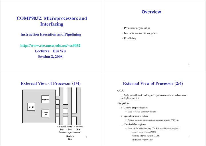
External View of Processor (1/4)

4

External View of Processor (2/4)

  • ALU

q Performs arithmetic and logical operations (addition, subtraction, multiplication etc).

  • Registers

q General purpose registers

v Used to stores temporary results.

q Special purpose registers

v Pointer registers, status register, program counter (PC) etc.

q User-invisible registers

v Used by the processor only. Typical user-invisible registers:

Memory buffer register (MBR) Memory address register (MAR)

Instruction register (IR)

slide-2
SLIDE 2

5

External View of Processor (3/4)

  • Control unit

q Controls the flow of information through the processor, and coordinates the activities of other units within it. q Its functions vary with its internal architecture.

v On a regular processor that executes x86 instructions natively, the control unit performs the tasks of fetching, decoding, managing execution and then storing results. v On a processor with a RISC core the control unit has significantly more work to do.

6

External View of Processor (4/4)

  • Buses

q Data bus

v Transfers data between the processor and other components (memory, I/O devices).

q Address bus

v Transfers the address from the processor to other components (memory, I/O devices).

q Control bus

v Transfers the control signals between the processor and other components (memory, I/O devices).

q Details will be covered later.

7

Internal View of Processor (1/2)

8

Internal View of Processor (2/2)

  • Status flags

q Indicate the intermediate or final state or outcome of arithmetic and logical operations. q Example flags include V (2’s complement oVerflow), S (Sign), Z (Zero) and C (Carry).

  • Shifter

q Performs shift operation.

  • Complementer

q Computes 2’s complement.

slide-3
SLIDE 3

9

Register Organization

  • space (temporary storage) for Processor
  • User-visible registers
  • User-invisible registers
  • Control and status registers
  • Number and function vary between processor designs
  • One of the major design decisions
  • Top level of memory hierarchy

10

User Visible Registers

May be referenced by means of the machine instructions.

  • General Purpose
  • Data
  • Address
  • Condition Codes

11

General Purpose Registers

  • May be true general purpose (any general-purpose register can

contain the operand for any opcode)

  • May be restricted (registers for floating-point and stack
  • perations)
  • May be used for data or addressing

q Data v Also called accumulator v r1~r31 in AVR. q Addressing v Segment registers

12

Address Registers

  • May be general purpose, or dedicated to a particular

addressing mode.

  • Segment pointers

q CS and DS in Pentium processors.

  • Index registers

q X, Y and Z in AVR.

  • Stack pointer

q SP in AVR.

slide-4
SLIDE 4

13

General Purpose vs. Specialized

  • Make them general purpose

q Increase flexibility and programmer options q Increase instruction size & complexity

  • Make them specialized

q Smaller (faster) instructions q Less flexibility

14

Program Status Registers

  • A set of bits storing key flags of the current program

execution

  • May be stored in one register or set of registers
  • Typical flags

q Sign q Zero q Carry q Equal q Overflow q Interrupt enable/disable q Operating modes

15

Operating Modes

Varies with processors. Typical operating modes:

q Supervisor mode v Allows privileged instructions to execute v Used by operating system v Not available to user programs

q User mode v Privileged instructions cannot be executed v Used by user program

16

Example Register Organizations

slide-5
SLIDE 5

17

Processor Cycle

  • All modern processors are synchronous machines.
  • Their timing is controlled by an external “clock” signal.

q This is just a square electric pulse that is supplied to the processor (and memory etc) by an external source time. q A processor running at 1GHz receives 109 clock pulses per second. v One pulse lasts 0.0000000001 second.

  • The processor operations are therefore broken up in cycles.

Time

18

Instruction Cycle

  • The instruction execution cycle is triggered by the clock

cycle, but has several stages:

q Each stage is triggered by successive clock pulses q The exact timing depends on the details of a particular processor

  • A complete instruction cycle usually takes several clock

cycles to execute.

  • The instruction cycle is divided into several stages.

q The number of stages vary with processors.

19

Indirect Cycle

  • May require memory access to fetch operands.
  • Indirect addressing requires more memory accesses.
  • Can be thought of as additional instruction subcycle.

20

Instruction Cycle with Indirect

slide-6
SLIDE 6

21

Instruction Cycle State Diagram

22

Data Flow (Instruction Fetch)

  • Depends on CPU design
  • In general, Fetch:

q PC contains address of next instruction q Address moved to MAR q Address placed on address bus q Control unit requests memory read q Result placed on data bus, copied to MBR, then to IR q Meanwhile PC incremented by 1

23

Data Flow (Data Fetch)

  • IR is examined.
  • If indirect addressing, indirect cycle is performed.

q Memory address is transferred to MAR. q Control unit requests memory read. q Result (address of operand) moved to MBR.

24

Data Flow (Fetch Diagram)

slide-7
SLIDE 7

25

Data Flow (Indirect)

26

Data Flow (Execute)

  • May take many forms
  • Depends on instruction being executed
  • May include

q Memory read/write q Input/Output q Register transfers q ALU operations

27

Data Flow (Interrupt)

  • Current PC saved to allow resumption after interrupt
  • Contents of PC copied to MBR
  • Special memory location (e.g. stack pointer) loaded

to MAR

  • MBR written to memory
  • PC loaded with address of interrupt handling routine
  • Next instruction (first of interrupt handler) can be

fetched

28

Data Flow (Interrupt)

slide-8
SLIDE 8

29

Instruction Pipelining

  • Break the instruction cycle into stages
  • Simultaneously work on each stage

30

Instruction Prefetch

  • Fetch accesses main memory
  • Execution usually does not access main memory
  • Can fetch next instruction during execution of current

instruction

q This is called instruction prefetch.

31

Two Stage Instruction Pipeline

Break instruction cycle into two stages:

  • FI: Fetch instruction
  • EI: Execute instruction

FI EI Clock cycle → 1 2 3 4 5 6 7 Instruction i Instruction i+1 Instruction i+2 Instruction i+3 Instruction i+4 FI EI EI EI EI FI FI FI

32

Two Stage Instruction Pipeline

  • But not doubled:

q Fetch usually shorter than execution q If execution involves memory accessing, the fetch stage has to wait q Any jump or branch means that prefetched instructions are not the required instructions

  • Add more stages to improve performance
slide-9
SLIDE 9

33

Six Stage Pipelining

  • Fetch instruction (FI)
  • Decode instruction (DI)
  • Calculate operands (CO)
  • Fetch operands (FO)
  • Execute instructions (EI)
  • Write operand (WO)

34

Timing for Six Stage Pipeline

35

Theoretical Performance of Pipeline

An ideal pipeline divides an instruction cycle into k stages.

q Each stage requires 1 time unit q The instruction cycle requires k time units

For n instructions, the execution times:

q With no pipelining: nk time units q With pipelining: k + (n-1) time units

Speedup of a k-stage pipeline is

q S = nk / [k+(n-1)] ≈ k (for large n)

36

The More Stages, the Better?

The overhead in moving information between pipeline stages and synchronization between pipeline stages increases with the number of pipeline stages. Pipeline hazards make it difficult to keep a large pipeline at the maximum rate.

slide-10
SLIDE 10

37

Pipeline Hazards

Pipeline hazards are situations that prevent the next instruction in the instruction stream from executing during its designated clock cycles.

q The instruction is said to be stalled. q If an instruction is stalled, all the following instructions are also installed.

Types of pipeline hazards:

q Structural hazards q Data hazards q Control hazards

38

Structural Hazards

A structural hazard occurs when multiple instructions need a resource ( e.g. memory) at the same time.

Instruction cycle → 1 2 3 4 5 6 7 8 9 10 11 12

LD R10, X

Instruction i+1 Instruction i+2 Instruction i+3 Instruction i+4 Instruction i+5 Instruction i+3 is stalled by one clock cycle

39

Data Hazards

A data hazard occurs when one instruction needs the result of another instruction, but the result is not available yet.

Instruction cycle → 1 2 3 4 5 6 7 8 9 10 11

MULT R2, R3

ADD R4, R0 Instruction i+2 ADD R4, R0 is stalled by two clock cycles MULT R2, R3 R1:R0 ← R2*R3 ADD R4, R0 R4 ← R4+R0

40

Control Hazards

Control hazards are caused by branch instructions. Consider the following example:

BRGE CS2121 SUB R12, R11

  • CS2121: ADD R2, R1

SUB R10, R9

slide-11
SLIDE 11

41

Control Hazards (Cont.)

Case 1: Branch is taken.

Instruction cycle → 1 2 3 4 5 6 7 8 9 10 11 BRGE CS2121 ADD R2, R1 stall SUB R10, R9 At this moment, both the condition (set by SUB) and the target address are known. Since the branch is taken, ADD R2, R1 will executed next. There is a penalty of 3 clock cycles in this case.

42

Control Hazards (Cont.)

Case 2: Branch is NOT taken.

Instruction cycle → 1 2 3 4 5 6 7 8 9 10 11 BRGE CS2121 SUB R12, R11 stall SUB R10, R9 At this moment, both the condition (set by SUB) and the target address are known. Since the branch is not taken, SUB R12, R11 will be executed next. There is a penalty of 2 clock cycles in this case.

43

Dealing with Branches

  • Prefetch Branch Target
  • Loop buffer
  • Branch prediction
  • Delayed branching

44

Prefetch Branch Target

  • Target of branch is prefetched in addition to instructions

following branch

  • Keep target until branch is executed
  • Used by IBM 360/91
slide-12
SLIDE 12

45

Loop Buffer

  • Very fast memory
  • Maintained by fetch stage of pipeline
  • Check buffer before fetching from memory
  • Very good for small loops or jumps
  • c.f. cache
  • Used by CRAY-1

46

Branch Prediction

  • Static prediction

q Predict never taken

v Assume that jump will not happen v 68020 & VAX 11/780

q Predict always taken

v Assume that jump will happen

47

Branch Prediction

  • Dynamic prediction

q One-bit prediction scheme v Used to record if the last execution resulted in a branch taken

  • r not. The system predicts the same behavior as for the last

time. q Two-bit prediction scheme v Used to record if the last two executions resulted in a branch taken or not. q Branch history table v Keep branch instruction address, history, target instruction (address) in a table in cache. v History info. can be used not only to predict the outcome of a conditional branch but also to avoid recalculation of the target address.

48

Delayed Branch

  • Do not take jump until you have to
  • Rearrange instructions

Consider the following example:

MULT R10, R9 CP R4, R3 MOVW R11:R10, R1:R0 BRGE CS2121 CP R4, R3 MULT R10, R9 BRGE CS2121 MOVW R11:R10 ADD R8, R3 ADD R8, R3

  • CS2121: INC R10 CS2121: INC R10
slide-13
SLIDE 13

49

Reading Material

1. Chapters 5&6. Computer Organization & Design: The HW/SW Interface by David Patterson and John Hennessy.