micromegas for muography the annecy station and detectors
play

Micromegas for muography, the Annecy station and detectors M. - PowerPoint PPT Presentation

Micromegas for muography, the Annecy station and detectors M. Chefdeville, C. Drancourt, C. Goy, J. Jacquemier, Y. Karyotakis, G. Vouters 21/12/2015, Arche meeting, AUTH Overview The station Technical review Detector performance


  1. Micromegas for muography, the Annecy station and detectors M. Chefdeville, C. Drancourt, C. Goy, J. Jacquemier, Y. Karyotakis, G. Vouters 21/12/2015, Arche meeting, AUTH

  2. Overview ● The station ● Technical review ● Detector performance (past testbeams) ● Plans in 2016 2

  3. The Annecy station 4 chambers of ~ 1x1 m 2 , each segmented into ~10 4 pads of 1x1 cm 2 Constructed and tested in 2012 for the CALICE SDHCAL (i.e. particle flow calorimetry) Revived a week ago after 3 years of sleep Current mechanical structure allow horiz. & vert. positions with 10 cm gaps between chb. Gas mixer and distribution PC (behind rack) Rack with RO- electronics & Telescope power (LV, HV) of 4 chb. 3

  4. The target Station installed temporarilly in a mechanical assembly hall (shared with other expt.) where it is possible to point at a close-by montain (Mt Veyrier) about 1 km away. Right now we actually point at its northen shoulder because of lack of space in the hall. Yellow structure (HESS camera handler prototype) blocking the view to the top. The hall gate is usually closed (thin metal sheet). 600 m 800 m 900 m 1000 m 500 m 4

  5. The station services For each chamber : Gas inlet/outlet (Ar/CO2 90/10 flushing 1 vol./h = 3 l/h) 7 HV 6 Bulk Micromegas + 1 drift plane Typically 500-700 V 2 LV For ASIC and readout boards (5V, 10 A) 3 USB For data transfer to PC 3 HDMI For clock distribution and synchronisation + PC, VME crate, CAEN HV, AMREL LV NIMA 729 (2013) 90 5

  6. The station detectors Prototypes designed for sampling calorimetry at a future linear collider (ILC, CLIC) → Compact design with front-end ASIC + Micromegas integrated on the PCB (=ASU) → Self-trigger electronics (hits are stored in a memory with a 200ns-timestamp) → Fine segmentation (pads of 1x1 cm 2 ) → Large-area (m 2 - size) 3 mm (Ar) gas gap → MPV = 15 electrons from a MIP {Active Sensor Unit, 32x48 cm 2 } x 6 → 1x1 m 2 prototype PCB with pads, font-end electronics (ASIC), flat inter-connects and Bulk Micromegas 6

  7. The front-end ASIC Charge preamplifier with a noise of 1500 ENC only (Cdet = 80 pF)! High sensitivity After gas multiplication, MIP signal is ~ 50000 electrons + channel-to-channel adjustable threshold 2 shapers followed by 3 discriminators , timestamping of 200 ns and 127 event depth memory Possibility to use an analogue readout, ADC on readout boards (requires an external trigger) Diodes for discharge protection inside the chip (+ diodes on the PCB) 7

  8. The DAQ system We are using a DAQ developed by LAPP and IPNL for operating the SDHCAL in 2012 Compatible with RPCs and Micromegas; successfully tested up to 50 layers (half a million channels !) Architecture based on Data Concentrator Cards (DCC) and Detector Interface boards (DIF) Software for small number of layers Labview based program Suitable for calibration and physics runs Provide easy control of all ASIC parameters DIF: interface between DAQ and detector Distribute power and clock to the ASIC Write ASIC configuration, read ASIC data Control acquisition signals (trigger, busy...) USB port → transmit data HDMI port → transmit clock and control signals 8 
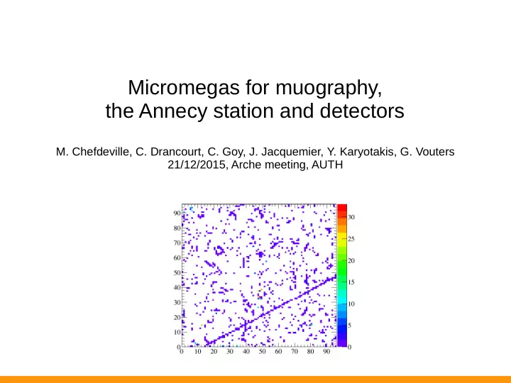
Screen capture of Labview window Acquisition with 4 chained ASUs

  9. Operating modes External trigger (for instance from PMT) Apply delay between trigger & readout Track hits easily found by looking at their time w.r.t. to readout time Internal trigger (generated by a chip when its memory is full) RAMULL signal sent from 1 chip to DAQ which sends it back to all chips Track hits found by looking at time coincidence in all chambers Event created when at least 1 hit in 3 chambers. Now, we do not have large enough scintillators to trigger so we use the RAMFULL mode. Makes event reconstruction efficiency dependent on chamber performance. Hit time in SDHCAL Ext. trigger Internal trigger 9

  10. TESTBEAMS 4 Micromegas prototypes of 1x1 m 2 constructed Tested at CERN in standalone and inside the CALICE RPC-SDHCAL Standalone test 150 GeV muons and pions → operational characteristics Excellent uniformity, noisy channel < 0.1 % CALICE SDHCAL Standalone setup 1 pion shower event 50 k pion shower events 10

  11. RESPONSE TO HIGH-ENERGY MUONS NIMA 763 (2014) 221 Response measurement inside the SDHCAL Beam muons (20-150 GeV) traverse the SDHCAL Use RPC layers as telescope → test Micromegas layers over whole area Build ASIC map → 144 regions of 8x8 cm 2 Excellent uniformity → track efficiency do not depend on position (except at ASU junctions) Multiplicity = 1.15 hit / muon Efficiency = 95%, var. 1% RMS Chb. 1 Chb. 2 Chb. 3 11

  12. NOISE DURING OPERATION (2/2) Readout when 1 ASIC memory is full (127 event depth) → relevant quantity is noise rate / ASIC 1 Hz/ASIC is achieved. Stable with time. In a horizontal position, one expects comparable rate for cosmics muons. Time information (200 ns clock) can be used to separate muon hits from noise hits. Noise / ASIC ~ 1 Hz Stability over time (17 hours) Chb. 1 Chb. 2 Chb. 3 12

  13. ANALOGUE READOUT Fast scintillator+PMT signal to trigger is sent to the chips to hold the shaper voltage. Readout all channel voltages takes time (~ 50 Hz acquisition rate for 4 chambers) Can be used to monitor the gas gain and possibly correct the mesh voltage accordingly. (do not work in internal trigger mode) 13

  14. First data from the station 3 of 4 chambers operational, vertical position 1 problematic chamber (known since 2012) One short on DIF readout (to be replaced) Two meshes do not hold HV Time for a fix ! Last week : took several hours of cosmics data at different HV to determine efficiency plateau Offline reconstruction of events on-going. Chamber 1 Chamber 2 Chamber 3 14

  15. Plans for the beginning of next year New structure available Enlarge gap between chambers (from 10 to 100 cm) to perform more precise measurement of track parameters. More space in assembly hall for us starting from January (point at montain top). Fix HV problems and replace DIF when mounting detectors on new structure. Chamber positions Acceptance (small gap) versus spatial resolution (large gap). First guess : optimal depends on distance to the target. To be determined with MC. Trigger Would be more efficiency to triggger on grazing muons. Mesh trigger unrealistic (24 of them !), 1x1 m 2 scintillators, hybrid detector stack (Sc.) Slow control Monitoring of P/T, study the possibility to correct (online) mesh voltage. Exp. protocol Measure (theta,phi) flux with no obstacle down to the horizon (test against MC). Measure (theta, phi) flux when pointing at the mountain. Produce a profile of Veyrier mountain. 15

Download Presentation
Download Policy: The content available on the website is offered to you 'AS IS' for your personal information and use only. It cannot be commercialized, licensed, or distributed on other websites without prior consent from the author. To download a presentation, simply click this link. If you encounter any difficulties during the download process, it's possible that the publisher has removed the file from their server.

Recommend


More recommend