Mechanics of Materials 13-1 Stress-Strain Curve for Mild Steel - - PowerPoint PPT Presentation

mechanics of materials 13 1
SMART_READER_LITE
LIVE PREVIEW

Mechanics of Materials 13-1 Stress-Strain Curve for Mild Steel - - PowerPoint PPT Presentation

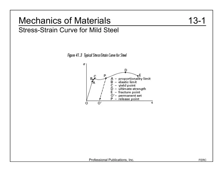
Mechanics of Materials 13-1 Stress-Strain Curve for Mild Steel Professional Publications, Inc. FERC Mechanics of Materials 13-2a Definitions Hookes Law Shear Modulus: Stress: Strain: Poissons Ratio: Normal


slide-1
SLIDE 1

Professional Publications, Inc.

FERC

13-1 Mechanics of Materials

Stress-Strain Curve for Mild Steel

slide-2
SLIDE 2

Professional Publications, Inc.

FERC

13-2a Mechanics of Materials

Definitions

  • Hooke’s Law
  • Shear Modulus:
  • Stress:
  • Strain:
  • Poisson’s Ratio:
  • Normal stress or strain =
  • Shear stress = || to the surface

to the surface

slide-3
SLIDE 3

Professional Publications, Inc.

FERC

13-2b Mechanics of Materials

Definitions

Uniaxial Load and Deformation Thermal Deformation

slide-4
SLIDE 4

Professional Publications, Inc.

FERC

13-3a Mechanics of Materials

Stress and Strain

Thin-Walled Tanks Hoop Stress: Axial Stress:

slide-5
SLIDE 5

Professional Publications, Inc.

FERC

13-3b Mechanics of Materials

Stress and Strain

Transformation of Axes

slide-6
SLIDE 6

Professional Publications, Inc.

FERC

13-3c Mechanics of Materials

Stress and Strain

Five simplified steps to construct Mohr’s circle 1. Determine the applied stresses (σx, σy, τxy). 2. Draw a set of σ-τ axes. 3. Locate the center: 4. Find the radius (or τmax): 5. Draw Mohr’s circle. c = 1

2 ( x + y).

slide-7
SLIDE 7

Professional Publications, Inc.

FERC

13-3d1 Mechanics of Materials

Stress and Strain

For examples 1 and 2, use the following illustration. Example 1 (FEIM) The principal stresses (σ2, σ1) are most nearly (A) –62 400 kPa and 14 400 kPa (B) 84 000 kPa and 28 000 kPa (C) 70 000 kPa and 14 000 kPa (D) 112 000 kPa and –28 000 kPa

slide-8
SLIDE 8

Professional Publications, Inc.

FERC

13-3d2 Mechanics of Materials

Stress and Strain

The center of Mohr’s circle is at max = (30000 kPa)

2 +(24000 kPa) 2 = 38419 kPa

1 = c max = (24000 kPa 38419 kPa) = 62419 kPa 2 = c + max = (24000 kPa +38419 kPa) = 14418 kPa Therefore, (D) is correct. Using the Pythagorean theorem, the radius of Mohr’s circle (τmax) is: c = 1

2 ( x + y) = 1 2 (48000 kPa +0) = 24000 kPa

slide-9
SLIDE 9

Professional Publications, Inc.

FERC

13-3d3 Mechanics of Materials

Stress and Strain

Example 2 (FEIM): The maximum shear stress is most nearly (A) 24 000 kPa (B) 33 500 kPa (C) 38 400 kPa (D) 218 000 kPa Therefore, (C) is correct. In the previous example problem, the radius of Mohr’s circle (τmax) was max = (30000 kPa)

2 +(24000 kPa) 2

= 38419 kPa (38400 kPa)

slide-10
SLIDE 10

Professional Publications, Inc.

FERC

13-3e Mechanics of Materials

Stress and Strain

General Strain Note that x is no longer proportional to x.

slide-11
SLIDE 11

Professional Publications, Inc.

FERC

13-3f Mechanics of Materials

Stress and Strain

Static Loading Failure Theory Maximum Normal Stress: A material fails if

  • Or
  • St

Sc This is true of brittle materials. For ductile materials: Maximum Shear Distortion Energy (von Mises Stress) Tmax = max 1 2 2 , 1 3 2 , 2 3 2

  • > Syt

2

  • =

1 2

1 2

( )

2 + 1 3

( )

2 + 2 3

( )

2

  • > Syt
slide-12
SLIDE 12

Professional Publications, Inc.

FERC

13-3g Mechanics of Materials

Stress and Strain

Torsion

  • For a body with radius r being

strained to an angle φ, the shear strain and stress are: = r d dz = G = Gr d dz

  • For a body with polar moment of

inertia (J), the torque (T) is: T = G d dz r

2dA A

  • = GJ d

dz The shear stress is: z = Gr T GJ = Tr J

  • For a body, the general angular

displacement (φ) is: = T GJ dz

L

  • For a shaft of length (L), the total

angular displacement (φ) is: Torsional stiffness:

slide-13
SLIDE 13

Professional Publications, Inc.

FERC

13-3h Mechanics of Materials

Stress and Strain

Hollow, Thin-Walled Shafts

slide-14
SLIDE 14

Professional Publications, Inc.

FERC

13-4a Mechanics of Materials

Beams

slide-15
SLIDE 15

Professional Publications, Inc.

FERC

13-4b Mechanics of Materials

Beams

Load, Shear, and Moment Relations Load: Shear: For a beam deflected to a radius of curvature (ρ), the axial strain at a distance (y) from the neutral axis is x = y /.

slide-16
SLIDE 16

Professional Publications, Inc.

FERC

13-4c1 Mechanics of Materials

Beams

Shear and Bending Moment Diagrams Example 1 (FEIM): Draw the shear and bending moment diagrams for the following beam.

slide-17
SLIDE 17

Professional Publications, Inc.

FERC

13-4c2 Mechanics of Materials

Beams

Shear is undefined at concentrated force points, but just short of x = 12 m Rl +Rr = 100 N m

  • 16 m

( ) = 1600 N

Rl = (8) Rr (4) = 0 Therefore, Rl = 533.3 N and Rr = 1066.7 N So the shear diagram is: From 0 m to 12 m, V = Rl 100 N m

  • x = 533.3 N 100 N

m

  • x; 0 m < x < 12 m

V(12

) = 533.3 N 100 N

m

  • (12 m) = 666.7 N

V = 1600 N 100 N m

  • x; 12 < x 16 m

From 12 m to 16 m, V =V(12

)+Rr (100 N)(x 12)

slide-18
SLIDE 18

Professional Publications, Inc.

FERC

13-4c3 Mechanics of Materials

Beams

The bending moment is the integral of the shear. M = Sdx

12

  • +

Sdx

12 x

  • = 800+

1600 N100 N m x

  • 12
  • dx

= 800 Nm+ 1600 N

( )x 50 N

m

  • x

2

  • 12

x

M = 533.3x – 50x2; 0 m < x < 12 m M = 800 Nm+ 1600 N

( )x 50 N

m

  • x

2 1600 N

( ) 12 m ( ) + 50 N

m

  • 12 m

( )

2

M = 12800 Nm+ 1600 N

( )x 50 N

m

  • x

2

12 m < x 16 m Or, let the right end of the beam be x = 0 m Then, S = 100 N m

  • x; 4 m < x 0 m

M = Sdx

x

  • =

100 N m

  • x
  • x = 50 N

m

  • x

2

slide-19
SLIDE 19

Professional Publications, Inc.

FERC

13-4c4 Mechanics of Materials

Beams

The bending moment diagram is:

slide-20
SLIDE 20

Professional Publications, Inc.

FERC

13-4d1 Mechanics of Materials

Beams

Example 2 (FEIM): The vertical shear for the section at the midpoint of the beam shown is (A) 0 (B) (C) P (D) none of these Drawing the force diagram and the shear diagram, Therefore, (A) is correct.

1 2 P

slide-21
SLIDE 21

Professional Publications, Inc.

FERC

13-4d2 Mechanics of Materials

Beams

Example 3 (FEIM): For the shear diagram shown, what is the maximum bending moment? The bending moment at the ends is zero, and there are no concentrated couples. (A) 8 kN • m (B) 16 kN • m (C) 18 kN • m (D) 26 kN • m Starting from the left end of the beam, areas begin to cancel after 2 m. Starting from the right end of the beam, areas begin to cancel after 4 m. The rectangle on the right has an area of 16 kN • m. The trapezoid on the left has an area of (1/2)(12 kN + 14 kN) (2 m) = 26 kN • m. The trapezoid has the largest bending moment. Therefore, (A) is correct.

slide-22
SLIDE 22

Professional Publications, Inc.

FERC

13-4e Mechanics of Materials

Beams

Bending Stress Deflection Shear Stress Note: Beam deflection formulas are given in the NCEES Handbook for any situation that might be on the exam.

slide-23
SLIDE 23

Professional Publications, Inc.

FERC

13-4f Mechanics of Materials

Beams

Example (FEIM): Find the tip deflection of the beam shown. EI is 3.47 × 10⁶ N • m2, the load is 11 379 N/m, and the beam is 3.7 m long. From the NCEES Handbook: = woL

4

8EI = 11379 N m

  • 3.7 m

( )

4

8

( ) 3.4710

6 Nm 2

( )

= 0.077 m

slide-24
SLIDE 24

Professional Publications, Inc.

FERC

13-5a Mechanics of Materials

Columns

Beam-Columns (Axially Loaded Beams) Maximum and minimum stresses in an eccentrically loaded column:

slide-25
SLIDE 25

Professional Publications, Inc.

FERC

13-5b Mechanics of Materials

Columns

Euler’s Formula Critical load that causes a long column to buckle: r = the radius of gyration k = the end-resistant coefficient kl = the effective length = slenderness ratio l r

slide-26
SLIDE 26

Professional Publications, Inc.

FERC

13-5c Mechanics of Materials

Columns

Elastic Strain Energy: Strain energy per unit volume for tension: