
SLIDE 1
FE Review-Mechanics of Materials 1
FE Review-Mechanics of Materials 1 FE Review-Mechanics of Materials - - PDF document
FE Review-Mechanics of Materials 1 FE Review-Mechanics of Materials 2 FE Review-Mechanics of Materials 3 FE Review-Mechanics of Materials 4 FE Review-Mechanics of Materials 5 FE Review-Mechanics of Materials 6 FE Review-Mechanics of
FE Review-Mechanics of Materials 1
FE Review-Mechanics of Materials 2
FE Review-Mechanics of Materials 3
FE Review-Mechanics of Materials 4
FE Review-Mechanics of Materials 5
FE Review-Mechanics of Materials 6
FE Review-Mechanics of Materials 7
FE Review-Mechanics of Materials 8
FE Review-Mechanics of Materials 9
FE Review-Mechanics of Materials 10
FE Review-Mechanics of Materials 11
FE Review-Mechanics of Materials 12
FE Review-Mechanics of Materials 13
FE Review-Mechanics of Materials 14
FE Review-Mechanics of Materials 15
FE Review-Mechanics of Materials 16
FE Review-Mechanics of Materials 17
FE Review-Mechanics of Materials 18
FE Review-Mechanics of Materials 19
FE Review-Mechanics of Materials 20
FE Review-Mechanics of Materials 21
FE Review-Mechanics of Materials 22
FE Review-Mechanics of Materials 23
FE Review-Mechanics of Materials 24
FE Review-Mechanics of Materials 25
FE Review-Mechanics of Materials 26
FE Review-Mechanics of Materials 27
FE Review-Mechanics of Materials 28
FE Review-Mechanics of Materials 29
FE Review-Mechanics of Materials 30
shown.
a-x = - 140 M Pa a-y = 205 MPa Txy = 100 MPa
What is the maximum shear stress? (A) 100 MPa (B) 160 MPa (C) 200 MPa (D) 210 MPa
tensile stress in the x-direction of 84 MPa, as well as shear stresses of 28 MPa, as shown.
y 84MPa
~
28 M Pa 28 MPa 84 MPa
~
X
Most nearly, what are the principal stresses? (A) 70 MPa; 14 MPa (B) 84 MPa; 28 MPa (C) 92 MPa; - 8.5 MPa (D) 112 MPa; - 28 MPa
FE Review-Mechanics of Materials 31
specimen shown if Fx= 3000 kN, E= 193 GPa, and v =0.29?
X
(A) - 4.0 X 10- 4 (B) - 1.1 X 10⁻⁴
(C) 1.0 X 10- 4
(D) 4.0 X 10- 4
dition shown. The maximum shear stress is 109.2 MPa.
'Txv-.,...-----
a-x = - 75 MPa a-y = 110 MPa Txy = 58 MPa
What are the orientations of the stress planes (relative to the x-axis)?
(A) -74°; 15° (B) - 58°; 32° (C) - 32°; 58°
(D) -16°; 74°
FE Review-Mechanics of Materials 32
bar ( cross section of 3 cm x 3 cm) shown when loaded to its yield point? The modulus of elasticity is 69 GPa, and the yield strength in tension is 255 MPa. Neglect the weight of the bar. (A) 3.3 mm (B) 9.3 mm (C) 12 mm (D) 15 mm
L = 2.5 m F
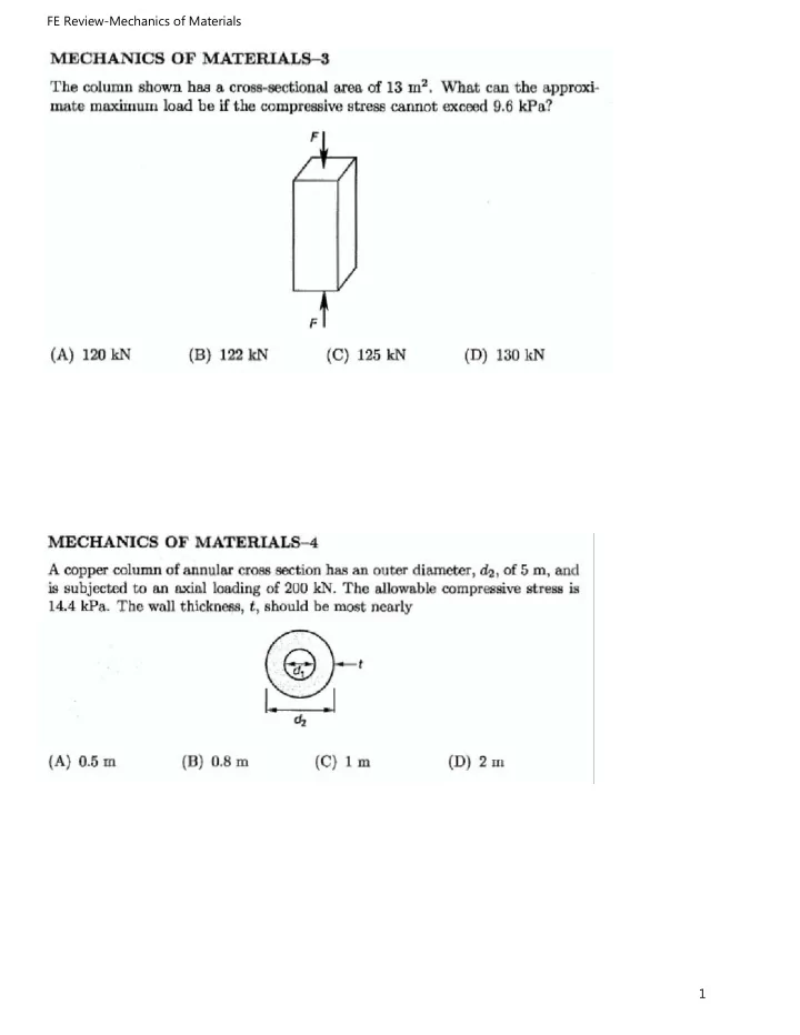
13 m2•
F
What is the approximate maximum load if the compres- sive stress cannot exceed 9.6 kPa? (A) 120 kN (B) 122 kN (C) 125 kN (D) 130 kN
FE Review-Mechanics of Materials 33
'Txy....,.;__
___
_ Ux = -310 MPa
uv = 250 MPa
'fxy=110MPa
The principal stresses are most nearly (A) 250 MPa; - 310 MPa (B) 270 MPa; - 330 MPa (C) 330 MPa; - 270 MPa (D) 310 MPa; -250 MPa
a and a shear modulus of G = 75 GP a, the shear strain is most nearly (A) 2.5 x 10⁻⁵ rad (B) 4.7 x 10⁻⁴ rad (C) 5.5 x 10- 4 rad (D) 8.3 x 10- 4 rad
FE Review-Mechanics of Materials 34
material? (A) 0.35 (B) 0.52 (C) 0.55 (D) 0.60
stresses shown.
y 120 MPa
~
_., 50 MPa 50 MPa 120 MPa
~
X
What is most nearly the maximum shear stress? (A) 50 MPa (B) 64 MPa (C) 72 MPa (D) 78 MPa
FE Review-Mechanics of Materials 35
shaft is 13 500 N-m. What is most nearly the maximum shear stress in the shaft? (A) 20 MPa (B) 23 MPa (C) 28 MPa (D) 34 MPa
a temperature change from 0°C to 50°C. The coefficient
2m I}
1.2 m
What is most nearly the change in area of the glass? (A) 0.00040 m2 (B) 0.0013 m2 (C) 0.0021 m2 (D) 0.0028 m2
FE Review-Mechanics of Materials 36
5 m high, and filled with a brine solution. Brine has a density of ll98 kg/ m3• The thickness of the steel shell is 12.5 mm. Neglect the weight of the tank.
5m
What is the approximate hoop stress in the steel 0.65 m above the rigid concrete pad? (A) (B)
(C)
(D)
1.2 MPa 1.4 MPa 7.2 MPa
1l MPa
\
diameter
= 50 mm
L = 1.0 m
Most nearly, what torque should be applied to the end
(A) 420 N-m (B) 560 N-m (C) 830 N-m (D) ll00 N-m
FE Review-Mechanics of Materials 37
110 MPa.
r1 = 0.015 m r2 = 0.025 m
What is most nearly the largest torque that can be applied? (A) 1700 N-m (B) 1900 N-m (C) 2300 N-m (D) 3400 N-m
25 mm in diameter and 50 cm long. One end is rigidly fixed to a support. Most nearly, what torque must be applied at the free end to twist the rod 4.5° about its longitudinal axis?
(A) 26 N-m (B) 84 N-m
(C) 110 N-m
(D) 170 N-m
FE Review-Mechanics of Materials 38
walls at both ends. The bar is 1000 mm long and has a cross- sectional area of 2600 mm2.
/A=
2600mm2
( )
1000 mm E = modulus of elasticity = 200 GPa
c, = coefficient of thermal expansion
= 9.4 x 10⁻⁶ 1/°C
What is most nearly the axial force in the bar if the temperature is raised to 40°C? (A) 92 kN (B) 110 kN (C) 130 kN (D) 150 kN
280 N-m at each end.
T
T
What is most nearly the maximum shear stress in the bar? (A) 2.2 Pa (B) 31 Pa (C) 42 Pa (D) 53 Pa
FE Review-Mechanics of Materials 39
rigid walls. The rod is initially unstressed, The rod's temperature subsequently increases 50°C. The rod is adequately stiffened and supported such that buckling does not occur. The coefficient of linear thermal expan- sion for steel is 11.7 x 10- 6 lj°C. The modulus of elas- ticity for steel is 210 GPa.
3.5 m
d= 12.5 mm
What is the approximate axial force in the rod? (A) 2.8 kN (B) 15 kN
(C) 19 kN
(D) 58 kN
temperature is 20°C. The linear coefficient of thermal expansion for the rails is 11 x 10-6 1/°C. The track is free to slide forward. Most nearly, how far apart will the ends of the track be when the temperature reaches 50°C? (A) 10.0009 km
(B) 10.0027 km
(C) 10.0033 km
(D) 10.0118 km
FE Review-Mechanics of Materials 40
pressure hull with an outside diameter of 3.5 m and a wall thickness of 15 cm constructed from a ductile mate-
pressure of 50 MPa. The hull should be designed as a (A) thin-walled pressure vessel using the outer radius in the stress calculations
(B) thin-walled pressure vessel using the logarithmic
mean area in stress calculations ( C) thin-walled pressure vessel using factors of safety
for brittle components such as viewing ports
(D) thick-walled pressure vessel
by a vertical force and a torque at its free end.
built-in end
Where is the maximum stress in the cylinder? (A) at the upper surface at midlength (L/2)
(B) at the lower surface at the built-in end
(C) at the upper surface at the built-in end (D) at both the upper and lower surfaces at the built-in end
FE Review-Mechanics of Materials 41
the other end is connected to a gear with an outside diameter of 40 cm as shown. The gear is subjected to a tangential gear force of 45 kN. The shear modulus of the aluminum is 2.8 x 10¹⁰ Pa.
fixed
d;=7.5cm
d0 = 10 cm 120 cm F =45kN ~
What are most nearly the maximum angle of twist and the shear stress in the shaft? (A) 0.016 rad, 14 MPa (B) 0.025 rad, 220 MPa (C) 0.057 rad, 67 MPa (D) 0.25 rad, 200 MPa
has an internal gage pressure of 8 MPa at the time of
If the steel has an allowable stress of 90 MPa, what is the required thickness of the wall? (A) 0.69 cm (B) 0.95 cm (C) 1.1 cm (D) 1.9 cm
FE Review-Mechanics of Materials 42
imum compressive stress at section D-D, 1.5 m from the left end?
12.5 cm
,,,_.,.,,.,
section D-D
(A) 63 MPa
(B) 110 MPa
(C) 230 MPa
(D) 330 MPa
45 kN
D
1
1--·_ _
1-·
A 3 m
B 1.5 m C
elasticity of the beam is 200 GPa; the moment of inertia is 4680 cm4 .
46.7 kg/m
A 1500 N t B
"
2.8 m
I
The upward force at B is 1500 N. What is most nearly the net deflection of the beam at a point 1.2 m from the fixed end? (A) - 0.32 mm (downward) (B) -0.29 mm (downward) (C) 0.12 mm (upward) (D) 0.17 mm (upward)
FE Review-Mechanics of Materials 43
1800 N 900 N
l~~ '~
t
1 m -i~,
What is most nearly the maximum bending moment? (A) 340 N-m
(B) 460 N-m
(C) 660 N-m (D) 890 N-m
The beam is manufactured from steel with a modulus of elasticit? of 210 GPa. The beam's cross-sectional area is 37.9 cm ; its moment of inertia is 2880 cm 4• The beam has a mass of 45.9 kg/ m. A 6000 N compressive force is applied at the top of the beam, at an angle of 30° from the horizontal. Neglect buckling.
q~ 30° ~I===-=_
1 ·
2m
What is most nearly the maximum shear force in the beam? (A) 3000 N (B) 3900 N (C) 5200 N (D) 6100 N
FE Review-Mechanics of Materials 44
nearly the force, F, necessary to deflect the rod a vertical distance of 7.5 mm?
F 7.5 mm
(A) 6900 N
(B) 8800 N
(C) 11000 N (D) 17000 N
t
10 cm diameter steel E = 210 GPa
310 N
4m
What is most nearly the maximum shear? (A) 500 N (B) 1000 N (C) 1500 N (D) 2000 N
FE Review-Mechanics of Materials 45
The beam is manufactured from steel with a modulus of elasticity of 200 GPa. The beam's cross-sectional area is 74 cm2; its moment of inertia is 8700 cm4. The beam has a mass of 60 kg/m. A 2500 N compressive force is applied at the top of the beam, at an angle of 22° from
2500 N
~22°
3m
What is most nearly the approximate maximum bend- ing moment in the beam? (A) 5000 N-m (B) 5200 N-m (C) 5900 N-m (D) 6100 N-m
wide x 10 cm deep and experiences a maximum shear
stress in the beam?
(A) 450 kPa
(B) 570 kPa (C) 680 kPa (D) 790 kPa
FE Review-Mechanics of Materials 46
tributed load as shown. The peak load at the right end
10 m
What is the approximate bending moment at a point
7 m from the left end of the beam? (A) 15 N-m (B) 17N-m (C) 28 N-m (D) 30N-m
The beam is manufactured from steel with a modulus of elasticity of 205 GPa. The beam's cross-sectional area is 86 cm2; its moment of inertia is 24400 cm4. A 3700 N compressive force is applied at the top of the beam, at an angle of 40° from horizontal. A counterclockwise moment of 600 N-m is applied to the free end. Neglect beam self-weight, and neglect buckling.
I:!====. ======:!.!
I},,m
1.6 m
What is most nearly the deflection at the tip of the beam due to the external force alone (i.e., neglecting the beam's own mass)?
(A) 0.63 mm
(B) 0.82 mm (C) 1.2 mm (D) 2.5 mm
FE Review-Mechanics of Materials 47
The beam is manufactured from steel with a modulus of elasticity of 205 GPa. The beam's cross-sectional area is 86 cm2; its moment of inertia is 24400 cm4. A 3700 N compressive force is applied at the top of the beam, at an angle of 40° from horizontal. A counterclockwise moment of 600 N-m is applied to the free end. Neglect beam self-weight, and neglect buckling.
I:!====. ======:!.!
I},,m
1.6 m
What is most nearly the deflection at the tip of the beam due to the external force alone (i.e., neglecting the beam's own mass)?
(A) 0.63 mm
(B) 0.82 mm (C) 1.2 mm (D) 2.5 mm
is 4 m in height and fixed at its base. The column is pinned against translation in its weak direction at the top but is unbraced in its strong direction. The column's modulus of elasticity is 2.1 x 10⁵ MPa. 4m
pinned in weak direction
\-\
12 cm
.\
fixed ;;
1
p;o 1D ! 16cm
\
',\
What is most nearly the maximum theoretical vertical load the column can support without buckling? (A) 1.3 MN (B) 5.2 MN
(C) 6.1 MN
(D) 11 MN
FE Review-Mechanics of Materials 48
sive force of 9000 N. The load is applied with an eccen- tricity of 2.5 cm along one of the lines of symmetry. What is most nearly the maximum tensile stress in the column? (A) 450 kPa (B) 900 kPa (C) 1400 kPa
(D) 2300 kPa
in a building to support a load of 5 MN. The maximum allowable stress in the column is 350 MPa. The column reacts linearly to all loads. If the contractor is permitted to load the column anywhere in the central one-fifth of the column's cross section, what are most nearly the smallest possible dimensions of the column? (A) 12 cm x 12 cm (B) 14 cm x 14 cm (C) 16 cm x 16 cm (D) 18 cm x 18 cm
FE Review-Mechanics of Materials 49
stress at A for the cantilever beam shown?
:,; A
7m 3m J,m 0}75 ,m
(A) (B)
(C)
(D)
350 N
elevation view
7.2 MPa 9.4 MPa 9.8 MPa 9.9 MPa
225 N
1-1
7.5cm cross section
5 . A rectangular steel bar 37.5 mm wide and 50 mm thick is pinned at each end and subjected to axial com-
75 m. The modulus of elasticity is 200 GPa. What is most nearly the critical buckling load?
(A) 60 kN
(B) 93 kN
(C) 110 kN
(D) 140 kN