MC - Compact Close Control Units DX version Down Flow DX version - - PDF document

mc compact close control units dx version down flow dx
SMART_READER_LITE
LIVE PREVIEW

MC - Compact Close Control Units DX version Down Flow DX version - - PDF document

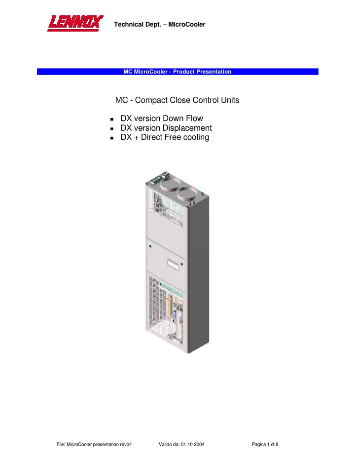
Technical Dept. MicroCooler MC MicroCooler - Product Presentation MC - Compact Close Control Units DX version Down Flow DX version Displacement DX + Direct Free cooling File: MicroCooler presentation rev04 Valido da: 01 10 2004


slide-1
SLIDE 1

Technical Dept. – MicroCooler

File: MicroCooler presentation rev04 Valido da: 01 10 2004 Pagina 1 di 8

MC MicroCooler - Product Presentation

MC - Compact Close Control Units

DX version Down Flow DX version Displacement DX + Direct Free cooling

slide-2
SLIDE 2

Technical Dept. – MicroCooler

File: MicroCooler presentation rev04 Valido da: 01 10 2004 Pagina 2 di 8

Products Description The micro coolers CCAC was developed according "DNP_P_04_02 rev00" MKTG specification for compete satisfy specific market needs. This units could be supplied only in DX version, down flow or displacement, frontal and side installation as shown in the following simplified drawings, In the upper part of the MC units can be installed a free cooling damper to allow the direct free cooling

  • peration : in this case the fresh air will be ducted to the unit by means of flexible D=200mm ducts connected

to the two (2) spigots on the top of the unit . Micro Coolers cover a range between 4.0 => 6.9 kW and have common design philosophy :

1.

Compact dimension L x D x H 600 x 300 x 1800 mm

2.

Suction from the front ( + from the top for direct free Cooling version )

3.

Backward curved blades fans (plug fans) complete with adjustable speed (170-190 Volts @ 20 Pa AESP)

4.

Evaporating coil positioned after the fans

5.

Hydrophilic treatment on the fins

6.

Thermostatic valve with MOP function (EEV as an option)

7.

Refrigerant connections from the top right side. Refrigerant shut off valves in the compressor compartement.

8.

Electrical connections with IP 65 connectors from the top left side

9.

Copeland Scroll compressors for sizes 045, 056, 070

  • 10. Daewoo Carrier Rotary Compressor for size 035
  • 11. Single phase power supply
slide-3
SLIDE 3

Technical Dept. – MicroCooler

File: MicroCooler presentation rev04 Valido da: 01 10 2004 Pagina 3 di 8

  • 1. Electrical panel. It is located in the middle of the unit and its door supports the LCD display.

2.

Electrical Connections. All connections are from the top by means of IP 65 plugs as shown in fig. 2. The male connectors are fixed on the unit; the female have to be removed and wired according the electrical drawing HF62000240 page 13.

  • The small 6 poles connector "C1" on the left back side is for unit's power supply,
  • The big 24 poles connector "C2" on the left side is for signals/alarms : the number of available

signals depends on the configuration of the units (alarm board Yes / alarm board Not)

  • The small 6 poles connector "C3" on the right side (not fixed on the unit's frame) is for the

remote condenser. Electrical Panel

  • Fig. 1
  • Fig. n° 2
slide-4
SLIDE 4

Technical Dept. – MicroCooler

File: MicroCooler presentation rev04 Valido da: 01 10 2004 Pagina 4 di 8

  • 3. Refrigerant Connections. The connections are located on the top right side (fig.2) and are provided

with rotalock adaptors. The refrigerant shut off valves are located into compressor compartement as shown in fig 3 for scrolls and fig 4 for rotary compressor (model MC 035) Hot gas shut

  • ff valve

Liquid line shut off valve Hot gas shut

  • ff valve

Liquid line shut off valve

  • Fig. 3
  • Fig. 4
slide-5
SLIDE 5

Technical Dept. – MicroCooler

File: MicroCooler presentation rev04 Valido da: 01 10 2004 Pagina 5 di 8

  • 4. Electronic expansion valve. The valve is located into compressor compartement as shown in fig. 5,

and it is fixed on the back side of the compartement

  • 5. Solenoid valve for start up operation. This component is only present in the smallest unit MC 035

equipped with rotary compressor: this kind of compressor doesn't allow the pressures equalisation during the stop phase and the single phase e-motor doesn't have a big starting torque. For this reason a solenoid valve between discharge and suction pipes is present: this valve opens when the compressor is switched off to allow the pressure equalisation and, at the same time, the check valve

  • n the discharge line avoids back flow from the condenser. [fig.6]

Electronic expansion valve By Pass Solenoid valve Check valve (behind compressor)

  • Fig. 6
  • Fig. 5
slide-6
SLIDE 6

Technical Dept. – MicroCooler

File: MicroCooler presentation rev04 Valido da: 01 10 2004 Pagina 6 di 8

  • 6. Air filters. For remove the filter, open the upper panel and simply extract the filter as shown in fig. 7.

The position and the overall dimensions are the same for G4 and F6 filters.

  • 7. Fans. The adopted fans are of the backward curved blades (Plug) type made from EBM Germany.

These components are equipped with an external rotor motor for the maximum efficiency and reliability and reduced sound emissions, even in fan speed modulation. For remove the fans, firstly remove the fan nozzles (accessible from the filter compartment), remove the two screws of the fan support, turn it up and extract the support with both fans (fig. 8).

  • Fig. 7
  • Fig. 8
slide-7
SLIDE 7

Technical Dept. – MicroCooler

File: MicroCooler presentation rev04 Valido da: 01 10 2004 Pagina 7 di 8

Technical data

** At 1,5 meters height, 2 meters frontal distance in free field – downflow version ( 20 Pa AESP) * With F6 filter the fan's speed have to be increased => increasing in sound emissions MC 070 MC 056 MC 045 MC 035 Power supply [ V/Ph/Hz ] 230/ 1 /50 230/ 1 /50 230/ 1 /50 230/ 1 /50 Air Flow @20 Pa AESP [ m3/h ] 1350 1230 1230 1050 Frame H [mm] 1800 1800 1800 1800 L [mm] 600 600 600 600 P [mm] 300 300 300 300 Weight [kg] 147 139 131 129 Compressor Type Scroll Scroll Scroll Rotary Cooling Capacity @ 27°C 40% UR – external air temp. 35°C [ kW ] 6.90 5.75 4.66 4.08 SHR [ - ] 0.91 0.96 0.98 1 Power consumption [ kW ] 1.97 1.51 1.23 1.05 Nominal Absorbed Current [ A ] 9.2 7.1 5.6 4.5 FLA [ A ] 14.8 11.4 10 8.8 LRA [ A ] 61 47 35 28 POE Oil charge [l] 1 1 0.74 0.74 Finned coil evaporator Front Surface [m2] 0.17 0.17 0.17 0.17 Geometry 25 x 21,65 25 x 21,65 25 x 21,65 25 x 21,65 Rows [ - ] 4 4 3 3 Type of fins [ - ] Hydrophilic Hydrophilic Hydrophilic Hydrophilic TFT (Total Free Cooling Temperature) [ °C ] 11.7 13.1 15.6 15.4 Fin pitch [ mm ] 1.8 1.8 1.8 1.8 Indoor fan Type Plug Plug Plug Plug Number of fans 2 2 2 2 Fans absorbed current @20 Pa AESP [ A ] 1.1 0.93 0.93 0.82 Fans absorbed power @20 Pa AESP [W] 240 210 210 185 Air Filter STD Filtration G4 G4 G4 G4 Overall surface [m2] 2.8 2.8 2.8 2.8 Electrical heaters Total Heating Capacity 1.6 1.6 1.6 1.6 N° of heaters [kW] 1 1 1 1 Material [ - ] Aluminium Aluminium Aluminium Aluminium Sound Data (*) Sound power level (with F6 filter) [dB(A)] 57 56 56 54 Sound pressure level** (with F6 filter) [dB(A)] 43 42 42 40 Sound power level (with G4 filter) [dB(A)] 55 54 54 52 Sound pressure level** (with G4 filter) [dB(A)] 41 40 40 38 Refrigerant Connections Rotalock 1/2" + 1m metallic flexible pipes Rotalock 1/2" + 1m metallic flexible pipes Rotalock 1/2" + 1m metallic flexible pipes Rotalock 1/2" + 1m metallic flexible pipes Refrigerant connection position Top of the unit Top of the unit Top of the unit Top of the unit

slide-8
SLIDE 8

Technical Dept. – MicroCooler

File: MicroCooler presentation rev04 Valido da: 01 10 2004 Pagina 8 di 8

Accessories MC Electrical heaters

  • HP Fans
  • Advanced µP with LCD Display
  • Electronic Expansion Valve
  • Air flow switch
  • Dirty filters switch
  • F6 filter
  • Smooke & fire sensor
  • Adjustable bse frame 100-400 mm
  • Insulating materials according german B1 classification
  • Plug connectors IP65
  • Emergency cooling 48Vcc (with free cooling option)
  • Flexible connection refrigerant side (metallic pipes) L=1000mm
  • Flexible connection air side L=3000mm D=200mm
  • Modulating damper for direct free cooling
  • Air flows configuration

Discharge ?

Down Front Top Rear

Suction from ?

Down N.A. N.A. N.A.

N:A:

Front

  • Displacement

N.A. N.A. Top

  • Displacement

N.A.

On request

Rear N.A.

N.A.

N.A. N.A.