
SLIDE 1
Rev 10/20/2015 Basic Rigging Safety Lecture-2015-10-20.pptm
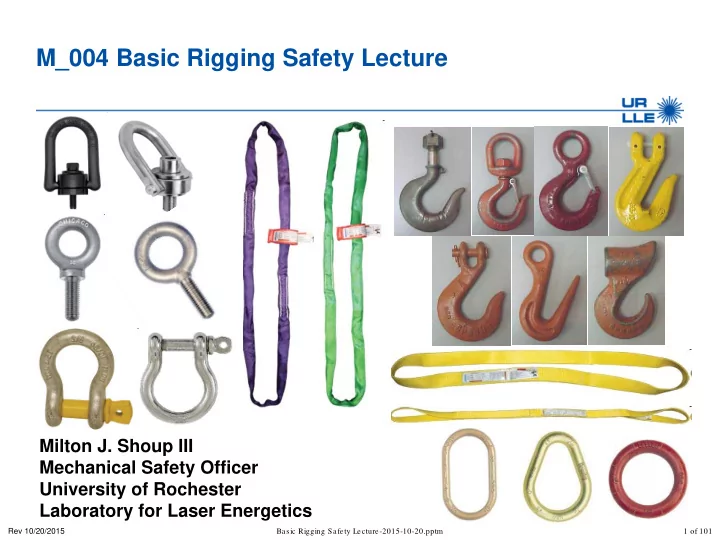
M_004 Basic Rigging Safety Lecture
Milton J. Shoup III Mechanical Safety Officer University of Rochester Laboratory for Laser Energetics
1 of 101
M_004 Basic Rigging Safety Lecture Milton J. Shoup III Mechanical - - PowerPoint PPT Presentation
M_004 Basic Rigging Safety Lecture Milton J. Shoup III Mechanical Safety Officer University of Rochester Laboratory for Laser Energetics Rev 10/20/2015 Basic Rigging Safety Lecture-2015-10-20.pptm 1 of 101 Summary Safety is everyones
Rev 10/20/2015 Basic Rigging Safety Lecture-2015-10-20.pptm
Milton J. Shoup III Mechanical Safety Officer University of Rochester Laboratory for Laser Energetics
1 of 101
Rev 10/20/2015 Basic Rigging Safety Lecture-2015-10-20.pptm
time to address concerns
equipment
rigging operation meet the required load ratings — If a rigger is unable to determine a proper rigging configuration contact ME or an Advanced Rigger for support Summary
2 of 101
follows; — hoist operator: an employee who generally uses an
performance of their regular job — rigger: At LLE a rigger is responsible for safely attaching payloads to the load hook of a hoist.
Rev 10/20/2015 Basic Rigging Safety Lecture-2015-10-20.pptm 3 of 101
Rev 10/20/2015 Basic Rigging Safety Lecture-2015-10-20.pptm
— Hoist operator – for overhead vertical lifting with unpowered horizontal motion — Overhead Crane operator – for overhead vertical lifting with powered horizontal motion
— No training is required for rigging payloads <120 lbs — Basic rigger – for personnel attaching any loads from 120-500 lbs to any hoist for a pure vertical lift — Advanced rigger – for personnel attaching any load >500 lbs to any hoist or any load using multiple load hooks Overhead rigging of material or equipment is to be performed only by designated personnel
4 of 101
Rev 10/20/2015 Basic Rigging Safety Lecture-2015-10-20.pptm
equipment; — Slings: Synthetic web slings, round and flat — Hardware: Hoist rings, eye bolts, shackles, hooks
activities for payloads up to 500 lbs; — Conduct rigging operations — Rig payloads for overhead lifts using the equipment listed above — Attach payloads to any load hook
5 of 101
Rev 10/20/2015 Basic Rigging Safety Lecture-2015-10-20.pptm
Slings and 29 CFR 1926.251 Rigging equipment for material handling
standards within the regulations
— There are 28 subparts to ASME B30
6 of 101
Rev 10/20/2015 Basic Rigging Safety Lecture-2015-10-20.pptm
(a) prevent or minimize injury to workers, and otherwise provide for the protection of life, limb, and property by prescribing safety requirements (b) provide direction to manufacturers, owners, employers, users, and
(c) guide governments and other regulatory bodies in the development, promulgation, and enforcement of appropriate safety directives
7 of 101
Rev 10/20/2015 Basic Rigging Safety Lecture-2015-10-20.pptm
selection, use, maintenance, and inspection — B30.1 Jacks — B30.9 Slings — B30.10 Hooks — B30.20 Below-the-Hook Lifting Devices — B30.26 Rigging Hardware
practices used at LLE
8 of 101
Rev 10/20/2015 Basic Rigging Safety Lecture-2015-10-20.pptm
1) Prep work a. Understand the payload b. Select the rigging gear c. Inspect all rigging gear d. Assign responsibilities 2) Attach the rigging gear to the payload 3) Attach payload to a load hook 4) Move the payload 5) Secure the payload 6) Detach the payload from a hook 7) Remove the rigging gear
9 of 101
Rev 10/20/2015 Basic Rigging Safety Lecture-2015-10-20.pptm
— Can often be found in “notes” section of a part drawing — Calculations (volume x density) — Talk to Mechanical Engineering
— Drawings will sometimes denote CG — Test lift to determine CG
— Know that destination is clear and ready to accept the payload — Insure the path is clear of any obstructions and personnel that will hinder movement
10 of 101
Rev 10/20/2015 Basic Rigging Safety Lecture-2015-10-20.pptm
— This includes hoist(s), bridges, jibs, or gantries
— This includes the shackles, hoist rings, straps, etc.
11 of 101
Rev 10/20/2015 Basic Rigging Safety Lecture-2015-10-20.pptm
— Visually inspect all hardware for damage including but not limited to screws, lifting shackles, hoist rings/lifting eyes, etc. — Look for thread damage, bent or fractured pieces, intentional or unintentional modifications
— Visually inspect for damage or fraying — Insure load rating tag is on the sling and legible — Inspect sewn threads Any rigging equipment that is found to be unsafe must removed from service immediately
12 of 101
Rev 10/20/2015 Basic Rigging Safety Lecture-2015-10-20.pptm
payload
— Example – Crane operator “Moving the load North” – Rigger “ Moving the load North aye”
13 of 101
Rev 10/20/2015 Basic Rigging Safety Lecture-2015-10-20.pptm
field
important to lifting loads with cranes and hoists
provide the same design factors and safety features as the load rated versions
14 of 101
rigging, often referred to as the horizontal angle.
employer's representative as being competent to perform specific duties
tool to assist in the performance of their regular job
“pull” is commonly used to describe line pull.
an applicable field, or certificate of professional standing, or who, by extensive knowledge, training, and experience, has successfully demonstrated the ability to solve or resolve problems relating to the subject matter and work.
Rev 10/20/2015 Basic Rigging Safety Lecture-2015-10-20.pptm 15 of 101
rigging hardware manufacturer. The terms "rated capacity" and "working load limit (WLL)" are commonly used to describe rated load.
load hook of a hoist.
Rev 10/20/2015 Basic Rigging Safety Lecture-2015-10-20.pptm 16 of 101
Rev 10/20/2015 Basic Rigging Safety Lecture-2015-10-20.pptm
17 of 101
Rev 10/20/2015 Basic Rigging Safety Lecture-2015-10-20.pptm
each of three basic styles; vertical, choker, and basket
rating is specified for a 90° sling angle Load
18 of 101
Rev 10/20/2015 Basic Rigging Safety Lecture-2015-10-20.pptm
— Type 3 Flat eye is the most popular for all three hitch styles — Type 4 Twisted eye is more commonly used for choker hitch
19 of 101
Rev 10/20/2015 Basic Rigging Safety Lecture-2015-10-20.pptm
— Manufacturers' name — Serial number — Load ratings (per hitch style) — Material — Length — Sling Type — Material
20 of 101
Rev 10/20/2015 Basic Rigging Safety Lecture-2015-10-20.pptm
— Heat damage may not be obvious — Any synthetic sling exposed to temperatures above 150 °F must be removed from service
21 of 101
Rev 10/20/2015 Basic Rigging Safety Lecture-2015-10-20.pptm
22 of 101
The red thread (tattletale) exposed in this example mean the sling must be removed from service. Simply remember “Red is dead”
Rev 10/20/2015 Basic Rigging Safety Lecture-2015-10-20.pptm
23 of 101
Rev 10/20/2015 Basic Rigging Safety Lecture-2015-10-20.pptm
shackles, hooks, etc.)
number web slings grouped together on a master link
24 of 101
Rev 10/20/2015 Basic Rigging Safety Lecture-2015-10-20.pptm
full load rating
reduce the load rating by as much as 50%
Angle of choke, deg Rated Capacity, % Over 120 100 90-120 87 60-89 74 30-59 62 0-29 49
25 of 101
Sling Angle
Rev 10/20/2015 Basic Rigging Safety Lecture-2015-10-20.pptm
1000 lbs 1000 lbs 1000 lbs 1000 lbs 1000 lbs
26 of 101
Rev 10/20/2015 Basic Rigging Safety Lecture-2015-10-20.pptm
Do’s
damage and remove from service if necessary
legible, and has all pertinent information
as necessary Don’ts
damaged
information is missing or not legible
shock loaded (remove it from service)
27 of 101
Rev 10/20/2015 Basic Rigging Safety Lecture-2015-10-20.pptm
28 of 101
Rev 10/20/2015 Basic Rigging Safety Lecture-2015-10-20.pptm
29 of 101
Rev 10/20/2015 Basic Rigging Safety Lecture-2015-10-20.pptm
30 of 101
Rev 10/20/2015 Basic Rigging Safety Lecture-2015-10-20.pptm
Never use a hoist ring if the swivel or bail bind, this is an indication of damage Bail Swivel
31 of 101
— Size – Ring size and thread size — Material – Commonly alloy steel or stainless steel — Thread length – Longer length usually designed for soft metals (aluminum) – Shorter lengths can be used in ferrous metals (steel)
Rev 10/20/2015 Basic Rigging Safety Lecture-2015-10-20.pptm 32 of 101
Rev 10/20/2015 Basic Rigging Safety Lecture-2015-10-20.pptm
Frame Size HR-125 Stock No. Working Load Limit Torque in Ft-Lbs Dimensions Weight Each Bolt Size Effective Thread Projection Length Radius Diameter No. (lbs.) A B C D E F G H (lbs.) 2 1016909 2500 28 1/2 - 13 x 2.00 0.7 4.85 1.96 0.87 0.69 3.35 2.29 2.33 2 1016912 2500 28 1/2 - 13 x 2.50 1.2 4.85 1.96 0.87 0.69 3.35 2.29 2.36 2 1016920 4000 60 5/8 - 11 x 2.00 0.7 4.85 1.96 0.87 0.69 3.35 2.16 2.41 2 1016924 4000 60 5/8 - 11 x 2.75 1.45 4.85 1.96 0.87 0.69 3.35 2.16 2.47 2 1016931 5000 100 3/4 - 10 x 2.25 0.95 4.85 1.96 0.87 0.69 3.35 2.04 2.52 2 1016935 5000 100 3/4 - 10 x 2.75 1.45 4.85 1.96 0.87 0.69 3.35 2.04 2.59 3 1016942 7000 100 3/4 - 10 x 2.75 0.89 6.57 2.96 1.36 0.94 4.87 2.98 6.72 3 1016946 7000 100 3/4 - 10 x 3.50 1.64 6.57 2.96 1.36 0.94 4.87 2.98 6.81
33 of 101
installation of the hoist ring
used for proper installation of the hoist ring
Rev 10/20/2015 Basic Rigging Safety Lecture-2015-10-20.pptm
34 of 101
Rev 10/20/2015 Basic Rigging Safety Lecture-2015-10-20.pptm
body
from service
final tightening
bolt is being threaded into — Approximately 1 times the diameter when threading into steel — Approximately 2 times the diameter when threading into aluminum
35 of 101
Rev 10/20/2015 Basic Rigging Safety Lecture-2015-10-20.pptm
36 of 101
Rev 10/20/2015 Basic Rigging Safety Lecture-2015-10-20.pptm
37 of 101
Rev 10/20/2015 Basic Rigging Safety Lecture-2015-10-20.pptm
38 of 101
Rev 10/20/2015 Basic Rigging Safety Lecture-2015-10-20.pptm
sensitive when pulling at an angle
— Size – Ring size and thread size — Material – Commonly forged from carbon steel or stainless steel (carbon steel and stainless steel have different load ratings for the same size) — Use angle – Can only be used up to 45°
39 of 101
Rev 10/20/2015 Basic Rigging Safety Lecture-2015-10-20.pptm
— straight vertical pulls only
— angular pulls up to 45° from vertical
40 of 101
Shoulder
Rev 10/20/2015 Basic Rigging Safety Lecture-2015-10-20.pptm
are based on a straight vertical pull “in a gradually increasing manner”
lower working load limits (see Shoulder Pattern) and should be avoided whenever possible
properly seated Shoulder Pattern eye bolt must be used
eye bolts in the plane of the eye, not at an angle to this plane
than a 45° pull
Working Load Limit Diameter and Thread Straight Pull (X) 45° Pull (Y) Shoulder Only 1/4"-20 500 125 5/16"-18 900 225 3/8"-16 1400 350 7/16"-14 2000 500 1/2"-13 2600 650 9/16"-12 3200 750 5/8"-11 4000 1000 3/4"-10 6000 1500 7/8"-9 7000 1750 1"-8 9000 2250 1-1/8"-7 12000 2500 1-1/4"-7 15000 3750 1-1/2"-6 21000 4900
41 of 101
Rev 10/20/2015 Basic Rigging Safety Lecture-2015-10-20.pptm
be used
42 of 101
Flat washers may be used under the shoulder to position the plane of the eye
Rev 10/20/2015 Basic Rigging Safety Lecture-2015-10-20.pptm
60°, the resultant sling angle is 30°
lateral load. The resultant load on the eye bolt is 1.73 lbf at 30°.
43 of 101
Rev 10/20/2015 Basic Rigging Safety Lecture-2015-10-20.pptm
marked with the WLL or required installation torque. The user must look up this information prior to use
rigging unless there are clearly legible identification marks
44 of 101
Rev 10/20/2015 Basic Rigging Safety Lecture-2015-10-20.pptm
shouldered eye bolts from two manufacturers shows different WLL
bolt for a side pull up to 45°
shouldered eye bolt for a side pull up to 90° (25% of in-line WLL), a maximum of 45° is permitted at LLE
information prior to use
Working Load Limit Diameter and Thread Chicago Straight Pull Crosby Straight Pull 1/4"-20 500 650 5/16"-18 900 1200 3/8"-16 1400 1550 7/16"-14 2000
2600 2600 9/16"-12 3200
4000 5200 3/4"-10 6000 7200 7/8"-9 7000 10600 1"-8 9000 13300 1-1/8"-7 12000 15000 1-1/4"-7 15000 21000 1-1/2"-6 21000 24000
45 of 101
Rev 10/20/2015 Basic Rigging Safety Lecture-2015-10-20.pptm
through the load sufficiently to allow full engagement of the nut
the load that the nut cannot be tightened securely against the load, use properly sized washers to take up the excess space BETWEEN THE NUT AND THE LOAD
and load so that when the nut is tightened securely, the shoulder is secured flush against the load surface
distance between the bottom of the load and the last thread of the eye bolt
B C,D 45° 90° A In-line
46 of 101
Pull angle
load
load
Rev 10/20/2015 Basic Rigging Safety Lecture-2015-10-20.pptm 47 of 101
Diameter
Rev 10/20/2015 Basic Rigging Safety Lecture-2015-10-20.pptm 48 of 101
Rev 10/20/2015 Basic Rigging Safety Lecture-2015-10-20.pptm
49 of 101
Rev 10/20/2015 Basic Rigging Safety Lecture-2015-10-20.pptm
and body
properly
than 1.5 times the diameter of the thread in steel and 2.5 times in aluminum
50 of 101
Rev 10/20/2015 Basic Rigging Safety Lecture-2015-10-20.pptm
markings
bolt axis
51 of 101
Rev 10/20/2015 Basic Rigging Safety Lecture-2015-10-20.pptm
52 of 101
Rev 10/20/2015 Basic Rigging Safety Lecture-2015-10-20.pptm
53 of 101
Rev 10/20/2015 Basic Rigging Safety Lecture-2015-10-20.pptm
between items — Strap to hoist ring or eyebolt — Strap to strap — Used as single attach point for multiple straps
— Size — Material
54 of 101
Rev 10/20/2015 Basic Rigging Safety Lecture-2015-10-20.pptm
55 of 101
Rev 10/20/2015 Basic Rigging Safety Lecture-2015-10-20.pptm
suspension or lifting applications where the load is strictly applied in-line
applications to gather multiple sling legs, or where side loading conditions may occur Round pin shackles are not approved for use at LLE
56 of 101
Rev 10/20/2015 Basic Rigging Safety Lecture-2015-10-20.pptm
applications.
recommends the use of bolt type shackles. Alternatively, the screw pin shall be secured from rotation or loosening.
involving side-loading circumstances
loading applications
rotated by a live line, such as a choker application
57 of 101
Screw pin shackles are preferred for use at LLE
Rev 10/20/2015 Basic Rigging Safety Lecture-2015-10-20.pptm
where round pin or screw pin shackles are used
long term installations and where the load may slide on the shackle pin causing the pin to rotate
utilizing a nut and cotter, eliminates the requirement to tighten pin before each lift or movement of load
58 of 101
Bolt-type shackles must have the cotter pin installed
Rev 10/20/2015 Basic Rigging Safety Lecture-2015-10-20.pptm
Working Load Limit ( 4 ¾ T) Manufacturer (Crosby) Size (3/4) 45° mark
59 of 101
Rev 10/20/2015 Basic Rigging Safety Lecture-2015-10-20.pptm
90° 45° In-line
Angle of Side Load from Vertical In-Line of shackle Adjusted WLL 0° In-Line 100% of Rated WLL 45° from In-Line 70% of Rated WLL 90° from In-Line 50% of Rated WLL
At LLE shackles are only permitted to be loaded in-line
60 of 101
90° from in-line In-line load
Rev 10/20/2015 Basic Rigging Safety Lecture-2015-10-20.pptm
included angle of 120° and can be utilized to full working load limit of the shackle
shackles
61 of 101
Rev 10/20/2015 Basic Rigging Safety Lecture-2015-10-20.pptm
acceptable
acceptable when the load is reasonably centered on the pin
62 of 101
Rev 10/20/2015 Basic Rigging Safety Lecture-2015-10-20.pptm
synthetic slings can occur when used with shackles
sling load rating and must be avoided
63 of 101
Rev 10/20/2015 Basic Rigging Safety Lecture-2015-10-20.pptm
be used and maintained
in the bow to prevent side loading
applied to the pin
rated load shall be reduced
line in a choker. The pin must go through the bow of the sling.
64 of 101
Rev 10/20/2015 Basic Rigging Safety Lecture-2015-10-20.pptm
recommendations
65 of 101
Rev 10/20/2015 Basic Rigging Safety Lecture-2015-10-20.pptm
66 of 101
Rev 10/20/2015 Basic Rigging Safety Lecture-2015-10-20.pptm
67 of 101
Rev 10/20/2015 Basic Rigging Safety Lecture-2015-10-20.pptm
68 of 101
Rev 10/20/2015 Basic Rigging Safety Lecture-2015-10-20.pptm
69 of 101
Rev 10/20/2015 Basic Rigging Safety Lecture-2015-10-20.pptm
70 of 101
attached to hoists — The overhead cranes use shank hooks with latches — The electric chain hoists use clevis hooks with latches
may be required
point loaded. All other types of hooks must not be point loaded.
Rev 10/20/2015 Basic Rigging Safety Lecture-2015-10-20.pptm 71 of 101
Rev 10/20/2015 Basic Rigging Safety Lecture-2015-10-20.pptm
tip of the hook
hook
latch must never support the load
under slack conditions
72 of 101
Rev 10/20/2015 Basic Rigging Safety Lecture-2015-10-20.pptm
Hook too big for eye Point loaded hook Eye bolt not seated
73 of 101
Rev 10/20/2015 Basic Rigging Safety Lecture-2015-10-20.pptm
angle between the legs is less than 90° and if the hook
latch
an intermediate link such as a master link or bolt type shackle to collect the legs of the slings. The intermediate link can be placed over the hook to provide an in-line load on the hook. This approach must also be used when using slings with three or more legs.
latch area and the latch closes
74 of 101
Rev 10/20/2015 Basic Rigging Safety Lecture-2015-10-20.pptm
75 of 101
Rev 10/20/2015 Basic Rigging Safety Lecture-2015-10-20.pptm
76 of 101
Rev 10/20/2015 Basic Rigging Safety Lecture-2015-10-20.pptm
legs Load
SlingTensi θ tan #
legs Load rce CollapseFo
The sling angle θ is always measured from the horizontal
77 of 101
Rev 10/20/2015 Basic Rigging Safety Lecture-2015-10-20.pptm
78 of 101
Rev 10/20/2015 Basic Rigging Safety Lecture-2015-10-20.pptm
79 of 101
Rev 10/20/2015 Basic Rigging Safety Lecture-2015-10-20.pptm
80 of 101
Sling tension will increase as the sling angle θ gets smaller
Rev 10/20/2015 Basic Rigging Safety Lecture-2015-10-20.pptm
81 of 101
Rev 10/20/2015 Basic Rigging Safety Lecture-2015-10-20.pptm
82 of 101
Rev 10/20/2015 Basic Rigging Safety Lecture-2015-10-20.pptm
83 of 101
Notice that at 30° the tension in the sling is equal to the Load
Rev 10/20/2015 Basic Rigging Safety Lecture-2015-10-20.pptm
84 of 101
Notice that at below 30° the tension in the sling is greater than Load
Rev 10/20/2015 Basic Rigging Safety Lecture-2015-10-20.pptm
— load buckling — exceeding the pad eye strength of where the hoist attaches to the load
85 of 101
Rev 10/20/2015 Basic Rigging Safety Lecture-2015-10-20.pptm
while the other two steady (balance) the load
equipment
86 of 101
Rev 10/20/2015 Basic Rigging Safety Lecture-2015-10-20.pptm
— All sides of the triangle are equal length
— The base of the triangle is twice the height
— The height is one-half of the sling length 60° 45° 30° L L L 2H H H 2H
87 of 101
Rev 10/20/2015 Basic Rigging Safety Lecture-2015-10-20.pptm
maximum included angle of 120° can be utilized to the full working load limit of the shackle
use a sling angle greater than 30°
88 of 101
Rev 10/20/2015 Basic Rigging Safety Lecture-2015-10-20.pptm
— Always use sling angles greater than 30° — For sling load calculations use Sling Tension = Load
to be performed — It either meets the load requirements or not (there is no such thing as just over the load capacity)
— do not reeve slings between attachment points
89 of 101
Rev 10/20/2015 Basic Rigging Safety Lecture-2015-10-20.pptm
required, they shall be placed in a shackle or bridle which is then placed
90 of 101
Rev 10/20/2015 Basic Rigging Safety Lecture-2015-10-20.pptm
single information are posted near the
signals is required for operation of the
signals is required for all riggers
91 of 101
Rev 10/20/2015 Basic Rigging Safety Lecture-2015-10-20.pptm
spaces because of close proximity and the use of radios
listed/posted hand signals
from a designated signalman (usually a rigger)
and it must be obeyed by the hoist operator
92 of 101
Rev 10/20/2015 Basic Rigging Safety Lecture-2015-10-20.pptm
93 of 101
Rev 10/20/2015 Basic Rigging Safety Lecture-2015-10-20.pptm
lifting conditions — Dan Neyland, Omega XOPS — Jeff Rodas, EP XOPS — Mark Romanofsky, ME — Milt Shoup, ME
94 of 101
Rev 10/20/2015 Basic Rigging Safety Lecture-2015-10-20.pptm
time to address concerns
equipment
rigging operation meet the required load ratings — If a rigger is unable to determine a proper rigging configuration contact ME or an Advanced Rigger for support Summary
95 of 101
components; Plain machinery eye bolt (WLL 2600 lb), synthetic sling (vertical WLL 10000 lb), Hoist (1T). What is the maximum payload? — 1300 lb — 2000 lb — 2600 lb — 10000 lb — Not enough information or not safe
Rev 10/20/2015 Basic Rigging Safety Lecture-2015-10-20.pptm 96 of 101
the following components; synthetic sling (basket WLL 10000 lb), and Hoist (4T). What is the maximum payload? — 4000 lb — 8000 lb — 10000 lb — Not enough information or not safe
Rev 10/20/2015 Basic Rigging Safety Lecture-2015-10-20.pptm 97 of 101
following individual components; Plain machinery eye bolts (WLL 2600 lb), synthetic slings (vertical WLL 1000 lb), Shackles (WLL 4T), and Hoist (5T). What is the maximum payload? — 1000 lb — 1300 lb — 2600 lb — 8000 lb — 10000 lb — Not enough information or not safe
angle provided
Rev 10/20/2015 Basic Rigging Safety Lecture-2015-10-20.pptm 98 of 101
following individual components; Plain machinery eye bolts (WLL 2600 lb), synthetic slings (vertical WLL 1000 lb), Shackles (WLL 4T), and Hoist (5T). The sling angle is 30°. What is the maximum payload? — 1000 lb — 1300 lb — 2600 lb — 8000 lb — 10000 lb — Not enough information or not safe
Rev 10/20/2015 Basic Rigging Safety Lecture-2015-10-20.pptm 99 of 101
following individual components; hoist rings (WLL 5000 lb), synthetic slings (vertical WLL 10000 lb), Shackles (WLL 4T), and Hoist (5T). The sling angle is 30°. What is the maximum payload? — 2500 lb — 5000 lb — 7500 lb — 8000 lb — 10000 lb — Not enough information or not safe
tension is equal to the load
Rev 10/20/2015 Basic Rigging Safety Lecture-2015-10-20.pptm 100 of 101
following individual components; hoist rings (WLL 5000 lb), synthetic slings (vertical WLL 10000 lb), Shackles (WLL 4T), and Hoist (5T). The sling angle is 30°. What is the maximum payload? — 2500 lb — 5000 lb — 7500 lb — 8000 lb — 10000 lb — Not enough information or not safe
Rev 10/20/2015 Basic Rigging Safety Lecture-2015-10-20.pptm 101 of 101