
1
5: DataLink Layer 5-1
Link Layer – Error Detection/Correction and MAC
5: DataLink Layer 5-2
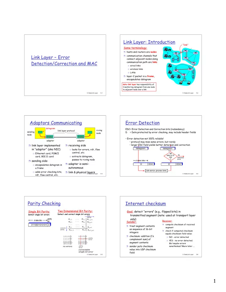
Link Layer: Introduction
Some terminology:
❒ hosts and routers are nodes ❒ communication channels that
connect adjacent nodes along communication path are links
❍ wired links ❍ wireless links ❍ LANs
❒ layer-2 packet is a frame,
encapsulates datagram “link”
data-link layer has responsibility of transferring datagram from one node to adjacent node over a link
5: DataLink Layer 5-3
Adaptors Communicating
❒ link layer implemented
in “adaptor” (aka NIC)
❍ Ethernet card, PCMCI
card, 802.11 card ❒ sending side:
❍ encapsulates datagram in
a frame
❍ adds error checking bits,
rdt, flow control, etc. ❒ receiving side
❍ looks for errors, rdt, flow
control, etc
❍ extracts datagram,
passes to rcving node ❒ adapter is semi-
autonomous
❒ link & physical layers
sending node frame rcving node datagram frame adapter adapter link layer protocol
5: DataLink Layer 5-4
Error Detection
EDC= Error Detection and Correction bits (redundancy) D = Data protected by error checking, may include header fields
- Error detection not 100% reliable!
- protocol may miss some errors, but rarely
- larger EDC field yields better detection and correction
5: DataLink Layer 5-5
Parity Checking
Single Bit Parity:
Detect single bit errors
Two Dimensional Bit Parity:
Detect and correct single bit errors
5: DataLink Layer 5-6
Internet checksum
Sender:
❒ treat segment contents
as sequence of 16-bit integers
❒ checksum: addition (1’s
complement sum) of segment contents
❒ sender puts checksum
value into UDP checksum field Receiver:
❒
compute checksum of received segment
❒
check if computed checksum equals checksum field value:
❍ NO - error detected ❍ YES - no error detected.
But maybe errors nonetheless? More later ….
Goal: detect “errors” (e.g., flipped bits) in transmitted segment (note: used at transport layer
- nly)