Wireless Ad Hoc & Sensor Networks Wireless Ad Hoc & Sensor - - PowerPoint PPT Presentation

wireless ad hoc sensor networks wireless ad hoc sensor
SMART_READER_LITE
LIVE PREVIEW

Wireless Ad Hoc & Sensor Networks Wireless Ad Hoc & Sensor - - PowerPoint PPT Presentation

Outline Wireless Ad Hoc & Sensor Networks Wireless Ad Hoc & Sensor Networks Multiple Access Technique Medium Access Control Application Designing Issues of MAC protocols Classification of MAC protocols Classification of


slide-1
SLIDE 1

Wireless Ad Hoc & Sensor Networks Wireless Ad Hoc & Sensor Networks

Medium Access Control

Application Transport Protocol N k P l

WS 2010/2011

Network Protocol Media Access Protocol

  • Prof. Dr. Dieter Hogrefe
  • Dr. Omar Alfandi

Media Access Protocol Physical Channel (Radio)

  • Dr. Omar Alfandi

Physical Channel (Radio)

Outline

  • Multiple Access Technique
  • Designing Issues of MAC protocols
  • Classification of MAC protocols

Classification of MAC protocols

  • Protocols examples
  • Characteristics of Link layer protocols
  • Characteristics of Link layer protocols
  • The lower layers in detail
  • Summary

2

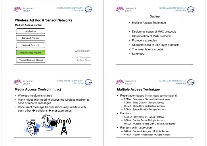
Media Access Control (Intro.)

  • Wireless medium is shared
  • Many nodes may need to access the wireless medium to

send or receive messages

  • Concurrent message transmissions may interfere with

each other  collisions  message drops

3

Multiple Access Technique

  • Reservation-based (Recall: mobile communication 1)

– FDMA : Frequency Division Multiple Access – TDMA : Time Division Multiple Access – CDMA : Code Division Multiple Access SDMA : Space Division Multiple Access – SDMA : Space Division Multiple Access

  • Random

– ALOHA : University of Hawaii Protocol ALOHA : University of Hawaii Protocol – CSMA : Carrier Sense Multiple Access – MACA : Multiple Access with Collision Avoidance

  • Random with reservation

– DAMA : Demand Assigned Multiple Access – PRMA : Packet Reservation Multiple Access

4

slide-2
SLIDE 2

Reservation-based

  • FDMA (Frequency Division Multiple Access)

– assign a certain frequency to a transmission channel – permanent (radio broadcast), slow hopping (GSM), fast hopping (FHSS, Frequency Hopping Spread Spectrum)

  • TDMA (Time Division Multiple Access)
  • TDMA (Time Division Multiple Access)

– assign a fixed sending frequency for a certain amount of time

  • CDMA (Code Division Multiple Access)

CDMA (Code Division Multiple Access)

  • SDMA (Space Division Multiple Access)

– segment space into sectors, use directed antennas g p , – Use cells to reuse frequencies

  • Combinations

5

FDD and TDD

  • In case of tow communicating parties sharing the

medium:

– Simplex : one way communication from sender to receiver – Duplex : two way communication between two parties – Frequency division duplex (FDD)

  • Combination of two simplex channels with different carrier

frequencies

– Time division duplex (TDD)

  • Time sharing of a single channel achieves quasi-simultaneous

Time sharing of a single channel achieves quasi simultaneous duplex transmission

6

Random Access

  • However, wireless communication is often much more

ad-hoc

– New terminals have to register with the network – Terminals request access to the medium spontaneously In many cases there is no central control – In many cases there is no central control

Other access methods such as distributed and non-arbitrated = random access non arbitrated = random access

7

Multiple Access

Characteristics:

  • Shared medium : radio channel is shared by an priori

unknown number of stations

  • Broadcast medium: all stations within transmission range
  • f a sender receive the signal

Challenge:

  • Wireless communication channel is prone to errors and

bl hidd / d d bl & i l problems, e.g., hidden/exposed node problems & signal attenuation

8

slide-3
SLIDE 3

Wired vs. Wireless

  • Ethernet uses 1-persistent CSMA/CD

– carrier sense multiple access with collision detection

  • Sense if the medium is free and start sending as soon as it

becomes free

  • While sending listen to the medium to detect other senders
  • In case of a collision immediately stop sending and wait for the

random amount of time

  • Problems in wireless networks
  • Problems in wireless networks

– signal strength decreases quickly with distance – senders apply CS and CD, but the collisions happen at receivers pp y , pp – Energy efficiency: having the radio turned on costs almost as much energy as transmitting, so to seriously save energy one needs to turn the radio off! needs to turn the radio off!

9

Outline

  • Multiple Access Technique
  • Designing Issues of MAC protocols

g g p

  • Classification of MAC protocols

Classification of MAC protocols

  • Protocols examples
  • Characteristics of Link layer protocols
  • Characteristics of Link layer protocols
  • The lower layers in detail
  • Summary

10

Need for MAC Protocols ?

  • Popular CSMA/CD (Carrier Sense Multiple

Access/Collision Detection) scheme is not applicable to wireless networks

  • CSMA suffers hidden terminal & exposed terminal

problems Collision Detection is impossible in wireless

  • Collision Detection is impossible in wireless

communication Specific MAC protocols for the access to the physical layer physical layer

11

Hidden Terminal Problem

  • A sends to B, C cannot receive A
  • C wants to send to B, C senses a “free” medium (CS

fails)

  • collision at B, A cannot receive the collision (CD fails)
  • A is “hidden” for C

B A C

12

slide-4
SLIDE 4

Exposed Terminal Problem

  • B sends to A, C wants to send to D
  • C has to wait, CS signals a medium in use
  • since A is outside the radio range of C waiting is not

necessary

  • C is “exposed” to B

B A C D B A C D

13

Near and Far Terminals

  • Terminals A and B send, C receives

– the signal of terminal B hides A’s signal – C cannot receive A

A B C

– This is also a severe problem for CDMA networks – precise power control required

14

Outline

  • Multiple Access Technique
  • Designing Issues of MAC protocols

g g p

  • Classification of MAC protocols
  • Protocols examples
  • Characteristics of Link layer protocols
  • Characteristics of Link layer protocols
  • The lower layers in detail
  • Summary

15

Classification of MAC protocols

16

slide-5
SLIDE 5

In general (1/2)

  • Contention-based protocols:

– A node does not make any resource reservation a priori. – Whenever a node receives a packet to be transmitted, it contends with its neighbour nodes for access – Can not provide QoS (Quality of Service) guarantees to session Can not provide QoS (Quality of Service) guarantees to session since nodes not guaranteed regular access to the channel

  • Contention-based with reservation

– Wireless networks may need to support real-time traffic R ti h i f i b d idth i i – Reservation mechanisms for reserving bandwidth a priori – Such protocols can provide QoS support to time-sensitive traffic sessions

17

In general (2/2)

  • Contention-based with scheduling

– These protocols focus on packet scheduling at nodes, and also h d li d f t th h l scheduling nodes for access to the channel – Used for enforcing priorities among flows whose packets are queued at nodes q – Some of them take into consideration battery characteristics (remaining battery power)

Oth t l

  • Other protocols

18

Outline

  • Multiple Access Technique
  • Designing Issues of MAC protocols

g g p

  • Classification of MAC protocols
  • Protocols examples

Protocols examples

  • Characteristics of Link layer protocols
  • Characteristics of Link layer protocols
  • The lower layers in detail
  • Summary

19

Multiple Access with Collision Avoidance (MACA)

  • MACA uses a two step signaling

procedure to address the hidden d d t i l bl

A B C D RTS

and exposed terminal problems

  • Use short signaling packets for

collision avoidance

CTS

collision avoidance

– Request (or ready) to send RTS: a sender requests the right to send

Data

b u s

q g from a receiver with a short RTS packet before it sends a data packet Clear to send CTS: the receiver

Data

s y b u s y

– Clear to send CTS: the receiver grants the right to send as soon as it is ready to receive

ACK

y 20

slide-6
SLIDE 6

MACA (cont.)

  • Signaling packets contain

– sender address – receiver address – packet size

  • Network allocation vector (NAV)
  • Network allocation vector (NAV)
  • Duration during which other sender have to keep quiet to avoid a

collision

  • If control (RTS-CTS) messages collide with each other
  • r with data packets, a backoff procedure is activated

(backoff is binary exponential) (backoff is binary exponential)

  • Example: Wireless LAN (IEEE 802.11)

21

MACA examples

  • MACA avoids the problem of hidden terminals

– A and C want to d t B send to B – A sends RTS first – C waits after receiving

RTS

C waits after receiving CTS from B

A B C CTS CTS

  • MACA avoids the problem of exposed terminals

– B wants to send to A, d C t D and C to D – now C does not have to wait as C cannot

RTS CTS RTS

receive CTS from A

A B C CTS D

22

MACA extensions (1/2)

  • MACAW extends MACA : RTS-CTS-DS-DATA-ACK

– DLL (Data Link Layer) acknowledgements – An improved backoff mechanism – DS (Data Sending) message:

  • Say that a neighbour of the sender overhears an RTS but not a CTS
  • Say that a neighbour of the sender overhears an RTS but not a CTS

(from the receiver)

  • In this case it can not tell if RTS-CTS was successful or not

Wh it h th DS it li th t th RTS CTS

  • When it overhears the DS, it realizes that the RTS-CTS was

successful, and it defers its own transmission

23

MACA extensions (2/2)

  • MACA –by invitation (MACA-BI) : RTR-DATA

– Is a receiver-initiated MAC protocol, the receiver node initiate d t t i i data transmission – It reduces the number of control packets used in the MACA protocol p – MACA-BI eliminate the need for the RTS packet, it uses RTR (ready to receive) control packet to the sender. RTR k t i i f ti b t th ti i t l d i – RTR packets carries information about the time interval during which the DATA packet would be transmitted – The efficiency of the MAC-BI scheme is mainly dependent on the y y p ability of the receiver node to predict accurately the arrival rates

  • f the traffic at the sender nodes.

24

slide-7
SLIDE 7

Media Access with Reduced Handshake (MARCH)

  • MARCH is receiver-initiated protocol
  • Unlike MACA-BI does not require any traffic prediction

mechanism

  • In MARCH the RTS packet is used only for the first

packet of the stream. From the second packet onward,

  • nly the CTS packet is used

Th t l l it th b d t t f th t ffi

  • The protocol exploits the broadcast nature of the traffic

to reduce the number of the handshakes involved in data transmission transmission

25

Reservation-based MAC protocol - DAMA

  • Demand Assigned Multiple Access (DAMA)
  • Practical systems therefore use reservation whenever

possible.

– But: Every scalable system needs an Aloha style component.

  • DAMA allows a sender to reserve timeslots. Two phase

approach R ti h

  • Reservation phase:

– a sender reserves a future time-slot – sending within this reserved time-slot is possible without collision sending within this reserved time-slot is possible without collision – reservation also causes higher delays

  • Termination phase: collision-free transmission using

p g reserved timeslots

26

DAMA: Explicit Reservation

  • Aloha mode for reservation: competition for small

reservation slots, collisions possible.

  • Reserved mode for data transmission within successful

reserved slots (no collisions possible).

  • It is important for all stations to keep the reservation list

consistent at any point in time and, therefore, all stations have to synchronize from time to time have to synchronize from time to time.

collisions Aloha Aloha Aloha Aloha t reserved reserved reserved reserved

27

PRMA: Implicit Reservation

  • Packet Reservation Multiple Access (PRMA)
  • A certain number of slots form a frame, frames are repeated.

St ti t f t l t di t th l tt d l h

  • Stations compete for empty slots according to the slotted aloha

principle.

  • Once a station reserves a slot successfully, this slot is automatically

y, y assigned to this station in all following frames.

  • Competition for this slots starts again as soon as the slot was empty

in the last frame

1 2 3 4 5 6 7 8 time-slot reservation

in the last frame .

frame1 frame2 1 2 3 4 5 6 7 8 time-slot A C D A B A F A C A B A ACDABA-F ACDABA-F reservation

2

frame3 frame4 collision at reservation attempts A B A F A B A F D AC-ABAF- A---BAFD frame5 attempts A C E E B A F D t ACEEBAFD

28

slide-8
SLIDE 8

Distributed PRMA

  • Every frame consists of n mini-slots and x data-slots
  • Every station has its own mini-slot and can reserve up to

k data-slots using this mini-slot (i.e. x = nk).

  • Other stations can send data in unused data-slots

according to a round-robin sending scheme (best-effort traffic)

N mini slots Nk data slots n=6 k=2 N mini-slots Nk data-slots n=6, k=2 reservations

  • ther stations can use free data-slots

for data-slots

  • ther stations can use free data slots

based on a round-robin scheme

29

Schedule-based MAC protocols – SMACS I

  • Given

– Many radio channels – super-frames of known length  Time synchronisation required

  • Goal: set up directional links between neighbouring

nodes nodes

– Link: radio channel + time slot at both sender and receiver – Free of collisions at receiver Free of collisions at receiver – Channel is picked randomly, slot is searched greedily until a collision free slot is found

  • Receivers sleep and only wake up in their assigned time

slots, once per super-frame

30

Schedule-based MAC protocols – SMACS II

  • Link Setup

– Case 1: Node A and B are both not connected

  • Node A sends invitation message
  • Node B answers that it is not connected to any other node
  • Node A tells B to pick slot/frequency for the link

p q y

  • Node B returns the link specification

– Case 2: Node A has neighbours and node B does not

N d A t th li k ifi ti d i t t N d B t it

  • Node A creates the link specification and instructs Node B to use it

– Case 3: Node A has no neighbours, but node B has some

  • Node B creates the link specification and instructs node A to use it

p

– Case 4: Both nodes have links to neighbours

  • Nodes exchange their schedules and pick free slots/frequencies in

mutual agreement mutual agreement

31

Schedule-based MAC protocols – TRAMA

  • TRAMA: Traffic-adaptive medium access protocol
  • Nodes are synchronised
  • Time is divided into cycles that consists of

– Random access periods – Scheduled access periods – Scheduled access periods

  • Nodes exchange neighbourhood information

– Learning about their two-hop neighbourhood by using the ‘neighbourhood exchange protocol’

  • In random access period send small incremental neighbourhood

update information in randomly selected time slots

  • Nodes exchange schedules

– Using the ‘schedule exchange protocol’

  • Similar to neighbourhood information exchange
  • Similar to neighbourhood information exchange

32

slide-9
SLIDE 9

Schedule-based MAC protocols – TRAMA II

  • As a result: Each node knows its two-hop neighbourhood and

the schedule

  • Problem
  • Problem

– How to decide which slot (in scheduled access period) to use?

  • Solution: ‘Adaptive Election’

– Use node identifier x and globally known hash function h – For time slot t, compute priority p as follows: p = h(x  t) – Compute this priority for next k time slots for the node itself and all Compute this priority for next k time slots for the node itself and all two-hop neighbours – Node can use those time slots for which it has the highest priority

t=0 t=1 t=2 t=3 t=4 t=0 t=1 t=2 t=3 t=4 A 23 9 56 3 26 B 64 8 12 44 6

Example: Priorities of node A and its two-hop neighbours B and C

C 18 6 33 57 2

neighbours B and C 33

Outline

  • Multiple Access Technique
  • Designing Issues of MAC protocols

g g p

  • Classification of MAC protocols
  • Protocols examples

Protocols examples

  • Characteristics of Link layer protocols
  • The lower layers in detail
  • Summary

34

Link Layer Protocols

  • Link Layer protocols cover the following topics

– Error Control

  • Make sure that the sent bits arrive and no other

 forward and backward error control

– Framing

  • Group bit sequence into packets/frames

 format, size

– Flow Control – Flow Control

  • Ensure that a fast sender does not overrun a slower receiver

– Link Management

  • Discovery and management of links to neighbouring nodes

Goal: Create a reliable communication link

35

Error control

  • Error control has to ensure that data transport is

– Error-free  deliver exactly the sent bits/packets – In-Sequence  deliver them in the original order – Duplicate-free  and at most once Loss free  and at least once – Loss-free  and at least once

  • Causes: fading, interferences, loss of bit synchronisation

– Results in bit errors packet losses Results in bit errors, packet losses

  • Mostly occurring in bursts

– In wireless networks high average bit error rates: 10-2 .. 10-4

  • Approaches

– Backward error control: ARQ (Automatic Repeat Request) – Forward error control: FEC (Forward Error Correction)

36

slide-10
SLIDE 10

Error control – ARQ

  • Idea of ARQ

– Transmitting node’s link layer accepts a data packet, creates a link-layer packet by adding a header and a checksum and link-layer packet by adding a header and a checksum and transmits this packet to the receiver – Receiver checks packet’s integrity with the help of the checksum and provides feedback; on negative feedback  retransmission and provides feedback; on negative feedback  retransmission

  • Standard ARQ Protocols

– Alternating bit g

  • Transmitter buffers one packet; single bit sequence number

– Go-back N

  • Buffer up to N packets; packets that were not ack are retransmitted

Buffer up to N packets; packets that were not ack. are retransmitted

– Selective Repeat/ Selective Reject

  • Sender and Receiver can buffer up to N packets; timer exceeds

missing packets are re requested missing packets are re-requested

37

Error control – FEC

  • Idea of FEC

– Transmitter accepts a stream or a block of user data or source bits add suitable redundancy and transmit the result to the sender add suitable redundancy and transmit the result to the sender – Depending on the amount and structure of dependency receiver can correct some bit errors

Source Channel Channel Digital Channel Encoder (FEC) Inter- leaver Modulator Information source Source symbols Channel symbols Channel symbols Digital waveform Tx antenna (FEC) Tx antenna Channel Channel decoder (FEC) Deinter- leaver Demodulator Information sink S Ch l Ch l Digital Rxantenna Source symbols Channel symbols Channel symbols g waveform 38

Error control – FEC

  • Block-coded FEC

– Block or a word of a number k of p-ary source symbols will be d t d bl k i ti f f h l b l used to produce a block consisting of n of q-ary channel symbols – Examples:

  • Reed-Solomon codes (RS)

( )

  • Bose-Chaudhuri-Hocquenghem codes (BCH)
  • Convolutional codes

– K bits of user data are mapped to n channel symbols; however, coding of two successive k-bit blocks is not independent

  • Also hybrid schemes i e combination of ARQ and FEC
  • Also hybrid schemes, i.e. combination of ARQ and FEC

exist

39

Framing

  • Packet size

– Small packets: Low packet error rate; high overhead Large packets: High packet error rate; low overhead – Large packets: High packet error rate; low overhead

  • Optimal packet size depends on

– Overhead – payload size – and bit error rate (BER)

F k BER ti l f l th i t d t i

  • For known BER optimal frame length is easy to determine
  • Problem: How to estimate BER? ( adaptive schemes)

Collect channel state information at the receiver (RSSI FEC ) – Collect channel state information at the receiver (RSSI, FEC, …)

  • Second problem: How long are observations valid? (aging)

– Only recent past is credible y p

40

slide-11
SLIDE 11

Link management

  • Goal

– Decide to which neighbours a link should be established

  • Problem: Link quality

– is not binary (good vs. bad), i.e. link quality has several characteristics characteristics – is time variable due to mobility, interferences, etc. – has to be estimated, actively by sending probe packets and , y y g p p evaluating Reponses or passively by overhearing

  • Establish a ‘neighbourhood table’ to store neighbouring

d d h i i d li k li i nodes and their associated link qualities

– Can be automatically constructed as part of MAC protocols

41

Link management – Link Quality Characteristics

  • Experiments show that the simple circular shape for the

region of communication is not realistic

– Instead

  • Irregular shape of the region of communication
  • Correlation between distance and loss rate is weak

Correlation between distance and loss rate is weak

  • Asymmetric links are rather frequent
  • Packet loss rate is time variable even when neighbours are

stationary  Significant short term variations stationary  Significant short-term variations

  • Regions of communication

– Effective region:

Link quality should be

Effective region: consistently >= 90% of packets arrive – Poor region: packet loss rates beyond 90%

y understood in a statistical and time- varying sense

– Transitional region: anything in between

42

Link quality estimation

  • How to estimate the quality of a link in the field?
  • Conflicting requirements

Precision – Precision

  • Collect enough results and give statistically meaningful results

– Agility

D t t i ifi tl h i li k diti i kl

  • Detect significantly changing link conditions quickly

– Stability

  • Estimation should be immune to short/transient fluctuations in the link

lit  i lti l l / t quality  averaging over multiple samples/events

– Efficiency

  • Reduce unnecessary link quality estimation effort to save energy
  • Passive vs. active estimators

– Active: node sends out special packets and collects responses – Passive: node observers transmissions in its neighbourhood Passive: node observers transmissions in its neighbourhood

43

Outline

  • Multiple Access Technique
  • Designing Issues of MAC protocols

g g p

  • Classification of MAC protocols
  • Protocols examples

Protocols examples

  • Characteristics of Link layer protocols
  • The lower layers in detail
  • The lower layers in detail
  • Summary

44

slide-12
SLIDE 12

802.11 – The lower layers in detail

  • PMD (Physical Medium Dependent)
  • MAC
  • PMD (Physical Medium Dependent)

– modulation, coding

  • PLCP (Physical Layer Convergence Protocol)

l h l t i l ( i

  • MAC

– access mechanisms – fragmentation encryption – clear channel assessment signal (carrier sense)

  • PHY Management

h l l ti PHY MIB – encryption

  • MAC Management

– Synchronization i – channel selection, PHY-MIB

  • Station Management

– coordination of all management functions – roaming – power management – MIB (management information b ) base) MAC LLC MAC Management DLC agement PMD PLCP MAC MAC Management PHY Management PHY D ation Man PMD P Sta

45

MAC layer: DFWMAC

  • Traffic services

Traffic services

– Asynchronous Data Service (mandatory)

  • exchange of data packets based on “best-effort”
  • support of broadcast and multicast
  • support of broadcast and multicast

– Time-Bounded Service (optional)

  • implemented using PCF (Point Coordination Function)
  • Access methods

– DFWMAC-DCF CSMA/CA (mandatory)

  • collision avoidance via binary exponential back-off mechanism

y p

  • minimum distance between consecutive packets
  • ACK packet for acknowledgements (not used for broadcasts)

– DFWMAC-DCF w/ RTS/CTS (optional) DFWMAC DCF w/ RTS/CTS (optional)

  • avoids hidden terminal problem

– DFWMAC-PCF (optional)

  • access point polls terminals according to a list
  • access point polls terminals according to a list

46

MAC layer

  • defined through different inter frame spaces
  • no guaranteed, hard priorities

SIFS (Sh t I t F S i )

  • SIFS (Short Inter Frame Spacing)

– highest priority, for ACK, CTS, polling response

  • PIFS (PCF IFS)

( )

– medium priority, for time-bounded service using PCF

  • DIFS (DCF, Distributed Coordination Function IFS)

l i i f h d i – lowest priority, for asynchronous data service PIFS DIFS DIFS t medium busy SIFS PIFS next frame contention di t if direct access if medium is free  DIFS

47

CSMA/CA

contention window (randomized back off medium busy DIFS DIFS next frame (randomized back-off mechanism) t medium busy next frame slot time direct access if medium is free  DIFS

  • station ready to send starts sensing the medium (Carrier Sense

based on CCA, Clear Channel Assessment)

  • if the medium is free for the duration of an Inter-Frame Space (IFS),

the station can start sending (IFS depends on service type)

  • if the medium is busy, the station has to wait for a free IFS, then the

station must additionally wait a random back-off time (collision y ( avoidance, multiple of slot-time)

  • if another station occupies the medium during the back-off time of

the station, the back-off timer stops (fairness) , p ( )

48

slide-13
SLIDE 13

CSMA/CA 2

  • Sending unicast packets

– station has to wait for DIFS before sending data – receivers acknowledge at once (after waiting for SIFS) if the packet was received correctly (CRC) – automatic retransmission of data packets in case of transmission automatic retransmission of data packets in case of transmission errors

DIFS SIFS DIFS ACK receiver sender data t data

  • ther

stations receiver DIFS t waiting time stations contention

49

Outline

  • Multiple Access Technique
  • Designing Issues of MAC protocols

g g p

  • Classification of MAC protocols
  • Protocols examples

Protocols examples

  • Characteristics of Link layer protocols
  • The lower layers in detail
  • The lower layers in detail
  • Summary

50

Summary

  • The most important design goal of a MAC protocol is to

enable shared access to the common wireless medium

  • The issues associated with the design of the MAC

protocol of wireless ad hoc networks are:

B d idth ffi i – Bandwidth efficiency – QoS support – Time-synchronization Time synchronization – Node mobility – Error-prone shared broadcast channel – Hidden and exposed problems – Distributed nature / lack of central coordination

51

Summary

  • The Ad Hoc wireless networks MAC protocols have been

classified into different categories

  • Some protocols were discussed as examples
  • In the MAC layer of the sensor networks lectures other

MAC protocols design issues will be discussed

  • Outlook: Next lecture will talk about routing protocols for

ad hoc networks

52

slide-14
SLIDE 14

Summary – Next Session

Application Transport Protocol Network Protocol Media Access Protocol Physical Channel (Radio)

53