Chapter 5: The Data Link Layer Chapter 5 Link Layer and LANs Our - - PDF document

chapter 5 the data link layer chapter 5 link layer and
SMART_READER_LITE
LIVE PREVIEW

Chapter 5: The Data Link Layer Chapter 5 Link Layer and LANs Our - - PDF document

Chapter 5: The Data Link Layer Chapter 5 Link Layer and LANs Our goals: understand principles behind data link layer services: error detection, correction sharing a broadcast channel: multiple access link layer addressing link


slide-1
SLIDE 1

Chapter 5 Link Layer and LANs

  • !!"#

$%&% !! " #$ &#'!& & '##! "! !&(" '&&&! "! # $)(*+,-,. //0122/ *#+,,##.!..

Computer Networking: A Top Down Approach 5th edition. Jim Kurose, Keith Ross Addison!Wesley, April 2009.

Chapter 5: The Data Link Layer

Our goals:

understand principles behind data link layer

services:

error detection, correction sharing a broadcast channel: multiple access

link layer addressing

  • 1

link layer addressing reliable data transfer, flow control: done!

instantiation and implementation of various link

layer technologies

Link Layer

5.1 Introduction and

services

5.2 Error detection

and correction

5.3Multiple access 5.6 Link!layer switches 5.7 PPP 5.8 Link virtualization:

ATM, MPLS

  • 3

5.3Multiple access

protocols

5.4 Link!layer

Addressing

5.5 Ethernet

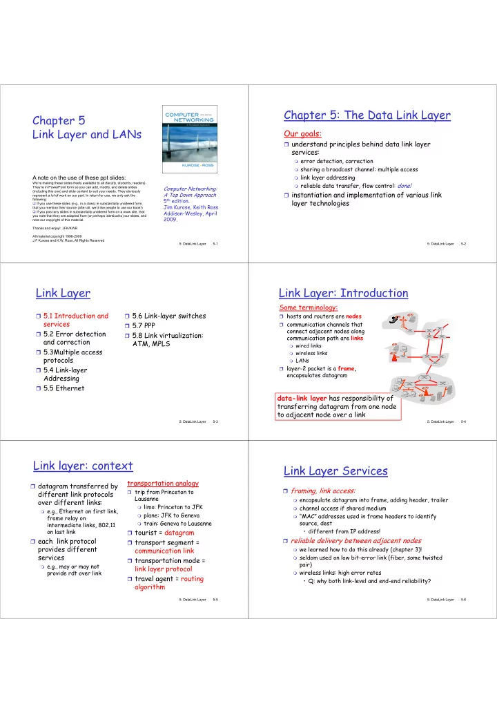
Link Layer: Introduction

Some terminology:

hosts and routers are communication channels that

connect adjacent nodes along communication path are

wired links wireless links

  • 4

wireless links LANs

layer!2 packet is a

encapsulates datagram

has responsibility of transferring datagram from one node to adjacent node over a link

Link layer: context

datagram transferred by

different link protocols

  • ver different links:

e.g., Ethernet on first link,

frame relay on intermediate links, 802.11

  • n last link

transportation analogy

trip from Princeton to

Lausanne

limo: Princeton to JFK plane: JFK to Geneva train: Geneva to Lausanne

tourist = datagram

  • n last link

each link protocol

provides different services

e.g., may or may not

provide rdt over link tourist = datagram transport segment =

communication link

transportation mode =

link layer protocol

travel agent = routing

algorithm

Link Layer Services

framing, link access:

encapsulate datagram into frame, adding header, trailer channel access if shared medium “MAC” addresses used in frame headers to identify

source, dest

  • different from IP address!
  • different from IP address!

reliable delivery between adjacent nodes

we learned how to do this already (chapter 3)! seldom used on low bit!error link (fiber, some twisted

pair)

wireless links: high error rates

  • Q: why both link!level and end!end reliability?
slide-2
SLIDE 2

Link Layer Services (more)

flow control:

pacing between adjacent sending and receiving nodes

error detection:

errors caused by signal attenuation, noise.

receiver detects presence of errors:

  • 5

receiver detects presence of errors:

  • signals sender for retransmission or drops frame

error correction:

receiver identifies and corrects bit error(s) without

resorting to retransmission half!duplex and full!duplex

with half duplex, nodes at both ends of link can transmit,

but not at same time

Where is the link layer implemented?

in each and every host link layer implemented in

“adaptor” (aka network interface card NIC)

Ethernet card, PCMCI

card, 802.11 card

  • &
  • 6

card, 802.11 card

implements link, physical

layer attaches into host’s

system buses

combination of

hardware, software, firmware

  • Adaptors Communicating
  • /

sending side:

encapsulates datagram in

frame

adds error checking bits,

rdt, flow control, etc. receiving side

looks for errors, rdt, flow

control, etc

extracts datagram, passes

to upper layer at receiving side

  • Link Layer

5.1 Introduction and

services

5.2 Error detection

and correction

5.3Multiple access 5.6 Link!layer switches 5.7 PPP 5.8 Link Virtualization:

  • ATM. MPLS
  • 2

5.3Multiple access

protocols

5.4 Link!layer

Addressing

5.5 Ethernet

Error Detection

EDC= Error Detection and Correction bits (redundancy) D = Data protected by error checking, may include header fields

  • Error detection not 100% reliable!
  • protocol may miss some errors, but rarely
  • larger EDC field yields better detection and correction
  • &

Parity Checking

Single Bit Parity:

  • Two Dimensional Bit Parity
  • 1
slide-3
SLIDE 3

Internet checksum (review)

Sender:

treat segment contents

as sequence of 16!bit Receiver:

compute checksum of

received segment

Goal: detect “errors” (e.g., flipped bits) in transmitted packet (note: used at transport layer only)

  • 3

as sequence of 16!bit integers

checksum: addition (1’s

complement sum) of segment contents

sender puts checksum

value into UDP checksum field received segment

check if computed checksum

equals checksum field value:

NO ! error detected YES ! no error detected.

But maybe errors nonetheless?

Checksumming: Cyclic Redundancy Check

view data bits, D, as a binary number choose r+1 bit pattern (generator), G goal: choose r CRC bits, R, such that

  • <D,R> exactly divisible by G (modulo 2)

receiver knows G, divides <D,R> by G. If non!zero remainder:

error detected! can detect all burst errors less than r+1 bits

  • 4

can detect all burst errors less than r+1 bits

widely used in practice (Ethernet, 802.11 WiFi, ATM)

CRC Example

Want: D.2r XOR R = nG equivalently: D.2r = nG XOR R equivalently:

  • equivalently:

if we divide D.2r by G, want remainder R R = remainder[ ] D.2r G

Link Layer

5.1 Introduction and

services

5.2 Error detection

and correction

5.3Multiple access 5.6 Link!layer switches 5.7 PPP 5.8 Link Virtualization:

ATM, MPLS

  • 5.3Multiple access

protocols

5.4 Link!layer

Addressing

5.5 Ethernet

Multiple Access Links and Protocols

Two types of “links”:

point!to!point

PPP for dial!up access point!to!point link between Ethernet switch and host

broadcast (shared wire or medium)

  • ld!fashioned Ethernet
  • 5
  • ld!fashioned Ethernet

upstream HFC 802.11 wireless LAN shared wire (e.g., cabled Ethernet) shared RF (e.g., 802.11 WiFi) shared RF (satellite) humans at a cocktail party (shared air, acoustical)

Multiple Access protocols

single shared broadcast channel two or more simultaneous transmissions by nodes:

interference

collision if node receives two or more signals at the same time

multiple access protocol

  • 6

distributed algorithm that determines how nodes

share channel, i.e., determine when node can transmit

communication about channel sharing must use channel

itself!

no out!of!band channel for coordination

slide-4
SLIDE 4

Ideal Multiple Access Protocol

Broadcast channel of rate R bps

  • 1. when one node wants to transmit, it can send at

rate R.

  • 2. when M nodes want to transmit, each can send at

average rate R/M

  • /

average rate R/M

  • 3. fully decentralized:

no special node to coordinate transmissions no synchronization of clocks, slots

  • 4. simple

MAC Protocols: a taxonomy

Three broad classes:

Channel Partitioning

divide channel into smaller “pieces” (time slots,

frequency, code)

allocate piece to node for exclusive use

Random Access

  • 12

Random Access

channel not divided, allow collisions “recover” from collisions

“Taking turns”

nodes take turns, but nodes with more to send can take

longer turns

Channel Partitioning MAC protocols: TDMA

TDMA: time division multiple access

access to channel in "rounds" each station gets fixed length slot (length = pkt

trans time) in each round

unused slots go idle

  • 1

unused slots go idle example: 6!station LAN, 1,3,4 have pkt, slots 2,5,6

idle

  • 6!slot

frame

Channel Partitioning MAC protocols: FDMA

FDMA: frequency division multiple access

channel spectrum divided into frequency bands each station assigned fixed frequency band unused transmission time in frequency bands go idle example: 6!station LAN, 1,3,4 have pkt, frequency

  • 11

example: 6!station LAN, 1,3,4 have pkt, frequency

bands 2,5,6 idle

frequency bands FDM cable

Random Access Protocols

When node has packet to send

transmit at full channel data rate R. no a priori coordination among nodes

two or more transmitting nodes ➜ “collision”, random access MAC protocol specifies:

  • 13

random access MAC protocol specifies:

how to detect collisions how to recover from collisions (e.g., via delayed

retransmissions) Examples of random access MAC protocols:

slotted ALOHA ALOHA CSMA, CSMA/CD, CSMA/CA

Slotted ALOHA

Assumptions:

all frames same size time divided into equal

size slots (time to transmit 1 frame) nodes start to transmit Operation:

when node obtains fresh

frame, transmits in next slot

if no collision: node can

send new frame in next

  • 14

transmit 1 frame)

nodes start to transmit

  • nly slot beginning

nodes are synchronized if 2 or more nodes

transmit in slot, all nodes detect collision if no collision: node can send new frame in next slot

if collision: node

retransmits frame in each subsequent slot with prob. p until success

slide-5
SLIDE 5

Slotted ALOHA

Pros Cons

  • 1

Pros

single active node can

continuously transmit at full rate of channel

highly decentralized:

  • nly slots in nodes

need to be in sync

simple

Cons

collisions, wasting slots idle slots nodes may be able to

detect collision in less than time to transmit packet

clock synchronization

Slotted Aloha efficiency

suppose: N nodes with

many frames to send,

max efficiency: find

p* that maximizes Np(1!p)

for many nodes, take

limit of Np*(1!p*) as N goes to infinity, gives: : long!run fraction of successful slots (many nodes, all with many frames to send)

  • 10

many frames to send, each transmits in slot with probability p

prob that given node

has success in a slot =

p(1!p) prob that any node has

a success = Np(1!p) as N goes to infinity, gives:

Max efficiency = 1/e = .37

At best: channel used for useful transmissions 37%

  • f time!

!

Pure (unslotted) ALOHA

unslotted Aloha: simpler, no synchronization when frame first arrives

transmit immediately

collision probability increases:

frame sent at t0 collides with other frames sent in [t0!1,t0+1]

  • 15

frame sent at t0 collides with other frames sent in [t0!1,t0+1]

Pure Aloha efficiency

P(success by given node) = P(node transmits) . P(no other node transmits in [p0!1,p0] . P(no other node transmits in [p0!1,p0] = p . (1!p) . (1!p) p . (1!p)

  • 16

p . (1!p) … choosing optimum p and then letting n !> infty ... = 1/(2e) = .18

even worse than slotted Aloha!

CSMA (Carrier Sense Multiple Access)

!"#: listen before transmit: If channel sensed idle: transmit entire frame

If channel sensed busy, defer transmission

  • 1/

human analogy: don’t interrupt others!

CSMA collisions

collisions can still occur:

propagation delay means two nodes may not hear each other’s transmission

collision:

spatial layout of nodes

  • 32

collision:

entire packet transmission time wasted

note:

role of distance & propagation delay in determining collision probability

slide-6
SLIDE 6

CSMA/CD (Collision Detection)

CSMA/CD: carrier sensing, deferral as in CSMA

collisions detected within short time colliding transmissions aborted, reducing channel

wastage collision detection:

  • 3

collision detection:

easy in wired LANs: measure signal strengths,

compare transmitted, received signals

difficult in wireless LANs: received signal strength

  • verwhelmed by local transmission strength

human analogy: the polite conversationalist

CSMA/CD collision detection

  • 31

“Taking Turns” MAC protocols

channel partitioning MAC protocols:

share channel efficiently and fairly at high load inefficient at low load: delay in channel access,

1/N bandwidth allocated even if only 1 active node!

  • 33

node! Random access MAC protocols

efficient at low load: single node can fully

utilize channel

high load: collision overhead

“taking turns” protocols look for best of both worlds!

“Taking Turns” MAC protocols

Polling:

master node

“invites” slave nodes to transmit in turn

typically used with

master

poll data

  • 34

typically used with

“dumb” slave devices

concerns:

polling overhead latency single point of

failure (master)

master slaves

data

“Taking Turns” MAC protocols

Token passing:

control passed

from one node to next sequentially.

token message

concerns:

T (nothing to send)

  • 3

concerns:

token overhead latency single point of failure

(token)

data to send) T

Summary of MAC protocols

channel partitioning, by time, frequency or code

Time Division, Frequency Division

random access (dynamic),

ALOHA, S!ALOHA, CSMA, CSMA/CD carrier sensing: easy in some technologies (wire), hard in

  • 30

carrier sensing: easy in some technologies (wire), hard in

  • thers (wireless)

CSMA/CD used in Ethernet CSMA/CA used in 802.11

taking turns

polling from central site, token passing Bluetooth, FDDI, IBM Token Ring

slide-7
SLIDE 7

Link Layer

5.1 Introduction and

services

5.2 Error detection

and correction

5.3Multiple access 5.6 Link!layer switches 5.7 PPP 5.8 Link Virtualization:

ATM, MPLS

  • 35

5.3Multiple access

protocols

5.4 Link!Layer

Addressing

5.5 Ethernet

MAC Addresses and ARP

32!bit IP address:

network!layer address used to get datagram to destination IP subnet

MAC (or LAN or physical or Ethernet)

  • 36

MAC (or LAN or physical or Ethernet)

address:

function: get frame from one interface to another

physically!connected interface (same network)

48 bit MAC address (for most LANs)

  • burned in NIC ROM, also sometimes software settable

LAN Addresses and ARP

Each adapter on LAN has unique LAN address

Broadcast address = FF!FF!FF!FF!FF!FF

1A!2F!BB!76!09!AD

  • 3/

= adapter

58!23!D7!FA!20!B0 0C!C4!11!6F!E3!98 71!65!F7!2B!08!53

LAN (wired or wireless)

LAN Address (more)

MAC address allocation administered by IEEE manufacturer buys portion of MAC address space

(to assure uniqueness)

analogy:

(a) MAC address: like Social Security Number

  • 42

(a) MAC address: like Social Security Number (b) IP address: like postal address

MAC flat address ➜ portability

can move LAN card from one LAN to another

IP hierarchical address NOT portable

address depends on IP subnet to which node is attached

ARP: Address Resolution Protocol

Each IP node (host,

router) on LAN has ARP table

ARP table: IP/MAC

address mappings for some LAN nodes Question: how to determine MAC address of B knowing B’s IP address?

1A!2F!BB!76!09!AD 137.196.7.78

  • 4

address mappings for some LAN nodes

< IP address; MAC address; TTL>

TTL (Time To Live): time

after which address mapping will be forgotten (typically 20 min)

1A!2F!BB!76!09!AD 58!23!D7!FA!20!B0 0C!C4!11!6F!E3!98 71!65!F7!2B!08!53

LAN

137.196.7.23 137.196.7.14 137.196.7.88

ARP protocol: Same LAN (network)

A wants to send datagram

to B, and B’s MAC address not in A’s ARP table.

A broadcasts ARP query

packet, containing B's IP address

dest MAC address = FF!

A caches (saves) IP!to!

MAC address pair in its ARP table until information becomes old (times out)

soft state: information

that times out (goes

  • 41

dest MAC address = FF!

FF!FF!FF!FF!FF

all machines on LAN

receive ARP query

B receives ARP packet,

replies to A with its (B's) MAC address

frame sent to A’s MAC

address (unicast)

that times out (goes away) unless refreshed ARP is “plug!and!play”:

nodes create their ARP

tables without intervention from net administrator

slide-8
SLIDE 8

Addressing: routing to another LAN

13+/720/8 909/2258848 ###

A

541//796++ 111#111#111#11 66811+42+

walkthrough: send datagram from A to B via R assume A knows B’s IP address

  • 43

R

111#111#111#112 ###2 774/9285 ###1

B

111#111#111#111 4/817501

two ARP tables in router R, one for each IP

network (LAN)

A creates IP datagram with source A, destination B A uses ARP to get R’s MAC address for 111.111.111.110 A creates link!layer frame with R's MAC address as dest,

frame contains A!to!B IP datagram

A’s NIC sends frame R’s NIC receives frame R removes IP datagram from Ethernet frame, sees its

destined to B

R uses ARP to get B’s MAC address This is a really important example – make sure you understand!

  • 44

R uses ARP to get B’s MAC address

R creates frame containing A!to!B IP datagram sends to B

R

13+/720/8 111#111#111#112 ###2 909/2258848 774/9285 ###1 ###

A

541//796++ 111#111#111#11 66811+42+

B

111#111#111#111 4/817501

Link Layer

5.1 Introduction and

services

5.2 Error detection

and correction

5.3Multiple access 5.6 Link!layer switches 5.7 PPP 5.8 Link Virtualization:

ATM and MPLS

  • 4

5.3Multiple access

protocols

5.4 Link!Layer

Addressing

5.5 Ethernet

Ethernet

“dominant” wired LAN technology:

cheap $20 for NIC first widely used LAN technology simpler, cheaper than token LANs and ATM kept up with speed race: 10 Mbps – 10 Gbps

  • 40

kept up with speed race: 10 Mbps – 10 Gbps

Metcalfe’s Ethernet sketch

Star topology

bus topology popular through mid 90s

all nodes in same collision domain (can collide with each

  • ther)

today: star topology prevails

active switch in center each “spoke” runs a (separate) Ethernet protocol (nodes

do not collide with each other)

  • 45

do not collide with each other)

switch

bus: coaxial cable star

Ethernet Frame Structure

Sending adapter encapsulates IP datagram (or other network layer protocol packet) in Ethernet frame

  • 46

Preamble:

7 bytes with pattern 10101010 followed by one

byte with pattern 10101011

used to synchronize receiver, sender clock rates

slide-9
SLIDE 9

Ethernet Frame Structure (more)

Addresses: 6 bytes

if adapter receives frame with matching destination

address, or with broadcast address (eg ARP packet), it passes data in frame to network layer protocol

  • therwise, adapter discards frame

Type: indicates higher layer protocol (mostly IP

  • 4/

Type: indicates higher layer protocol (mostly IP

but others possible, e.g., Novell IPX, AppleTalk)

CRC: checked at receiver, if error is detected,

frame is dropped

Ethernet: Unreliable, connectionless

connectionless: No handshaking between sending and

receiving NICs

unreliable: receiving NIC doesn’t send acks or nacks

to sending NIC

stream of datagrams passed to network layer can have gaps

  • 2

stream of datagrams passed to network layer can have gaps

(missing datagrams)

gaps will be filled if app is using TCP

  • therwise, app will see gaps

Ethernet’s MAC protocol: unslotted CSMA/CD

Ethernet CSMA/CD algorithm

  • 1. NIC receives datagram

from network layer, creates frame

  • 2. If NIC senses channel idle,

starts frame transmission If NIC senses channel

  • 4. If NIC detects another

transmission while transmitting, aborts and sends jam signal

  • 5. After aborting, NIC

enters $%

  • If NIC senses channel

busy, waits until channel idle, then transmits

  • 3. If NIC transmits entire

frame without detecting another transmission, NIC is done with frame ! enters $% : after mth collision, NIC chooses K at random from

{0,1,2,…,2!1}. NIC waits

K·512 bit times, returns to Step 2

Ethernet’s CSMA/CD (more)

Jam Signal: make sure all

  • ther transmitters are

aware of collision; 48 bits Bit time: .1 microsec for 10 Mbps Ethernet ; for K=1023, wait time is about 50 msec Exponential Backoff:

Goal: adapt retransmission

attempts to estimated current load

heavy load: random wait

will be longer first collision: choose K from

  • 1

about 50 msec

first collision: choose K from

{0,1}; delay is K· 512 bit transmission times

after second collision: choose

K from {0,1,2,3}…

after ten collisions, choose K

from {0,1,2,3,4,…,1023} See/interact with Java applet on AWL Web site: highly recommended !

CSMA/CD efficiency

Tprop = max prop delay between 2 nodes in LAN ttrans = time to transmit max!size frame

  • 3

efficiency goes to 1

as tprop goes to 0 as ttrans goes to infinity

better performance than ALOHA: and simple,

cheap, decentralized!

  • 802.3 Ethernet Standards: Link & Physical Layers

many different Ethernet standards

common MAC protocol and frame format different speeds: 2 Mbps, 10 Mbps, 100 Mbps,

1Gbps, 10G bps

different physical layer media: fiber, cable

  • 4
  • &
  • :7
  • 228;9$<

228;9$4 228;9+< 228;9$1 228;9;< 228;98<

fiber physical layer copper (twister pair) physical layer

slide-10
SLIDE 10

Manchester encoding

  • used in 10BaseT

each bit has a transition allows clocks in sending and receiving nodes to

synchronize to each other

no need for a centralized, global clock among nodes!

Hey, this is physical!layer stuff!

Link Layer

5.1 Introduction and

services

5.2 Error detection

and correction

5.3 Multiple access 5.6 Link!layer switches 5.7 PPP 5.8 Link Virtualization:

ATM, MPLS

  • 5.3 Multiple access

protocols

5.4 Link!layer

Addressing

5.5 Ethernet

Hubs

… physical!layer (“dumb”) repeaters:

bits coming in one link go out all other links at

same rate

all nodes connected to hub can collide with one

another

no frame buffering

  • 5

no frame buffering

no CSMA/CD at hub: host NICs detect

collisions

twisted pair hub

Switch

link!layer device: smarter than hubs, take

active role

store, forward Ethernet frames examine incoming frame’s MAC address,

selectively forward frame to one!or!more

  • utgoing links when frame is to be forwarded on
  • 6
  • utgoing links when frame is to be forwarded on

segment, uses CSMA/CD to access segment transparent

hosts are unaware of presence of switches

plug!and!play, self!learning

switches do not need to be configured

Switch: allows multiple simultaneous transmissions

hosts have dedicated,

direct connection to switch

switches buffer packets Ethernet protocol used on

each incoming link, but no

A B C’ 1 2 3 4 5 6

  • /

each incoming link, but no collisions; full duplex

each link is its own collision

domain switching: A!to!A’ and B!

to!B’ simultaneously, without collisions

not possible with dumb hub

A’ B’ C switch with six interfaces (1,2,3,4,5,6) 4 5

Switch Table

Q: how does switch know that

A’ reachable via interface 4, B’ reachable via interface 5?

A: each switch has a switch

table, each entry:

A B C’ 1 2 3 4 5 6

  • 02

table, each entry:

(MAC address of host, interface

to reach host, time stamp) looks like a routing table! Q: how are entries created,

maintained in switch table?

something like a routing

protocol?

A’ B’ C switch with six interfaces (1,2,3,4,5,6) 4 5

slide-11
SLIDE 11

Switch: self!learning

switch learns which hosts

can be reached through which interfaces

when frame received,

switch “learns” location of sender: incoming LAN

A B C’ 1 2 3 4 5 6 A A’

Source: A Dest: A’

  • sender: incoming LAN

segment

records sender/location

pair in switch table

A’ B’ C 4 5 MAC addr interface TTL Switch table (initially empty) A 1 60

Switch: frame filtering/forwarding

When frame received:

  • 1. record link associated with sending host
  • 2. index switch table using MAC dest address

&entry found for destination '(

  • 01

'( dest on segment from which frame arrived ' drop the frame forward the frame on interface indicated ) flood forward on all but the interface

  • n which the frame arrived

Self!learning, forwarding: example

A B C’ 1 2 3 4 5 6 A A’

Source: A Dest: A’

A A’ A A’ A A’ A A’ A A’

frame destination

unknown: flood

destination A

  • 03

A’ B’ C 4 5 MAC addr interface TTL Switch table (initially empty) A 1 60 A’ A

destination A

location known:

A’ 4 60

selective send

Interconnecting switches

switches can be connected together

A B S1 C D F S2 S4 S3 I

  • 04

B

Q: sending from A to G ! how does S1 know to

forward frame destined to F via S4 and S3?

A: self learning! (works exactly the same as in

single!switch case!)

C D E H I G

Self!learning multi!switch example

Suppose C sends frame to I, I responds to C

A B S1 C D F S2 S4 S3 I 1 2

  • Q: show switch tables and packet forwarding in S1,

S2, S3, S4

B C D E H I G

Institutional network

to external network router mail server web server

  • 00

IP subnet

slide-12
SLIDE 12

Switches vs. Routers

both store!and!forward devices

routers: network layer devices (examine network layer

headers)

switches are link layer devices

routers maintain routing tables, implement routing

algorithms

  • 05

algorithms

switches maintain switch tables, implement

filtering, learning algorithms

Link Layer

5.1 Introduction and

services

5.2 Error detection

and correction

5.3Multiple access 5.6 Hubs and switches 5.7 PPP 5.8 Link Virtualization:

ATM

  • 06

5.3Multiple access

protocols

5.4 Link!Layer

Addressing

5.5 Ethernet

Point to Point Data Link Control

  • ne sender, one receiver, one link: easier than

broadcast link:

no Media Access Control no need for explicit MAC addressing e.g., dialup link, ISDN line

  • 0/

e.g., dialup link, ISDN line

popular point!to!point DLC protocols:

PPP (point!to!point protocol) HDLC: High level data link control (Data link

used to be considered “high layer” in protocol stack!

PPP Design Requirements [RFC 1557]

packet framing: encapsulation of network!layer

datagram in data link frame

carry network layer data of any network layer

protocol (not just IP) at same time

ability to demultiplex upwards

bit transparency: must carry any bit pattern in the

  • 52

bit transparency: must carry any bit pattern in the

data field

error detection (no correction) connection liveness: detect, signal link failure to

network layer

network layer address negotiation: endpoint can

learn/configure each other’s network address

PPP non!requirements

no error correction/recovery no flow control

  • ut of order delivery OK

no need to support multipoint links (e.g., polling)

  • 5

Error recovery, flow control, data re!ordering all relegated to higher layers!

PPP Data Frame

Flag: delimiter (framing) Address: does nothing (only one option) Control: does nothing; in the future possible

multiple control fields

Protocol: upper layer protocol to which frame

  • 51

Protocol: upper layer protocol to which frame

delivered (eg, PPP!LCP, IP, IPCP, etc)

slide-13
SLIDE 13

PPP Data Frame

info: upper layer data being carried check: cyclic redundancy check for error

detection

  • 53

Byte Stuffing

“data transparency” requirement: data field must be allowed to include flag pattern <01111110>

Q: is received <01111110> data or flag?

Sender: adds (“stuffs”) extra < 01111110> byte

  • 54

Sender: adds (“stuffs”) extra < 01111110> byte

after each < 01111110> data byte

Receiver:

two 01111110 bytes in a row: discard first byte,

continue data reception

single 01111110: flag byte

Byte Stuffing

flag byte pattern in data to send

  • 5

flag byte pattern plus stuffed byte in transmitted data

PPP Data Control Protocol

Before exchanging network! layer data, data link peers must

configure PPP link (max.

frame length, authentication)

  • 50

authentication)

learn/configure network

layer information

for IP: carry IP Control

Protocol (IPCP) msgs (protocol field: 8021) to configure/learn IP address

Link Layer

5.1 Introduction and

services

5.2 Error detection

and correction

5.3Multiple access 5.6 Hubs and switches 5.7 PPP 5.8 Link Virtualization:

ATM and MPLS

  • 55

5.3Multiple access

protocols

5.4 Link!Layer

Addressing

5.5 Ethernet

Virtualization of networks

Virtualization of resources: powerful abstraction in systems engineering:

computing examples: virtual memory, virtual

devices

Virtual machines: e.g., java

  • 56

Virtual machines: e.g., java IBM VM os from 1960’s/70’s

layering of abstractions: don’t sweat the details of

the lower layer, only deal with lower layers abstractly

slide-14
SLIDE 14

The Internet: virtualizing networks

1974: multiple unconnected nets

ARPAnet data!over!cable networks packet satellite network (Aloha)

packet radio network

… differing in:

addressing conventions packet formats error recovery routing

  • 5/

packet radio network

ARPAnet satellite net

=% % >&' =! ?#7!.#,!'999$ 7 ! :!/54!#035046#

The Internet: virtualizing networks

Internetwork layer (IP):

addressing: internetwork

appears as single, uniform entity, despite underlying local network heterogeneity

network of networks

Gateway:

“embed internetwork packets in

local packet format or extract them”

route (at internetwork level) to

next gateway

  • 62

ARPAnet satellite net gateway

Cerf & Kahn’s Internetwork Architecture

What is virtualized?

two layers of addressing: internetwork and local

network

new layer (IP) makes everything homogeneous at

internetwork layer underlying local network technology

  • 6

underlying local network technology

cable satellite 56K telephone modem today: ATM, MPLS

… “invisible” at internetwork layer. Looks like a link layer technology to IP!

ATM and MPLS

ATM, MPLS separate networks in their own

right

different service models, addressing, routing

from Internet

viewed by Internet as logical link connecting

  • 61

viewed by Internet as logical link connecting

IP routers

just like dialup link is really part of separate

network (telephone network) ATM, MPLS: of technical interest in their

  • wn right

Asynchronous Transfer Mode: ATM

**+,-++''%(155Mbps to

622 Mbps and higher) Broadband Integrated Service Digital Network architecture

Goal: integrated, end!end transport of carry voice,

video, data meeting timing/QoS requirements of voice, video

  • 63

meeting timing/QoS requirements of voice, video

(versus Internet best!effort model)

“next generation” telephony: technical roots in

telephone world

packet!switching (fixed length packets, called

“cells”) using virtual circuits

ATM architecture

physical ATM AAL physical ATM AAL physical ATM physical ATM end system end system switch switch

  • 64

adaptation layer: only at edge of ATM network

data segmentation/reassembly roughly analagous to Internet transport layer

ATM layer: “network” layer

cell switching, routing

physical layer

end system end system switch switch

slide-15
SLIDE 15

ATM: network or link layer?

Vision: end!to!end transport: “ATM from desktop to desktop”

ATM is a network

technology Reality: used to connect

ATM network IP network

  • 6

Reality: used to connect IP backbone routers

“IP over ATM” ATM as switched

link layer, connecting IP routers

ATM Adaptation Layer (AAL)

ATM #%. (AAL): “adapts” upper

layers (IP or native ATM applications) to ATM layer below

AAL present , not in switches AAL layer segment (header/trailer fields, data)

  • 60

AAL layer segment (header/trailer fields, data)

fragmented across multiple ATM cells

analogy: TCP segment in many IP packets physical ATM AAL physical ATM AAL physical ATM physical ATM end system end system switch switch

ATM Adaptation Layer (AAL) [more]

Different versions of AAL layers, depending on ATM service class:

AAL1: for CBR (Constant Bit Rate) services, e.g. circuit emulation AAL2: for VBR (Variable Bit Rate) services, e.g., MPEG video AAL5: for data (eg, IP datagrams)

  • 65

AAL PDU ATM cell User data

ATM Layer

Service: transport cells across ATM network

analogous to IP network layer very different services than IP network layer >& ; : 8& @ $ 7 AB

  • 66

' $: $: $: $:

  • 78.

?8. 8. C8.

  • "
  • ATM Layer: Virtual Circuits

VC transport: cells carried on VC from source to dest

call setup, teardown for each call before data can flow each packet carries VC identifier (not destination ID) every switch on source!dest path maintain “state” for each

passing connection

link,switch resources (bandwidth, buffers) may be allocated to

  • 6/

link,switch resources (bandwidth, buffers) may be allocated to

VC: to get circuit!like perf. Permanent VCs (PVCs)

long lasting connections typically: “permanent” route between to IP routers

Switched VCs (SVC):

dynamically set up on per!call basis

ATM VCs

Advantages of ATM VC approach:

QoS performance guarantee for connection

mapped to VC (bandwidth, delay, delay jitter)

Drawbacks of ATM VC approach:

Inefficient support of datagram traffic

  • /2

Inefficient support of datagram traffic

  • ne PVC between each source/dest pair) does

not scale (N*2 connections needed)

SVC introduces call setup latency, processing

  • verhead for short lived connections
slide-16
SLIDE 16

ATM Layer: ATM cell

5!byte ATM cell header 48!byte payload

Why?: small payload !> short cell!creation delay

for digitized voice

halfway between 32 and 64 (compromise!)

  • /

halfway between 32 and 64 (compromise!)

Cell header Cell format

ATM cell header

/ 0 virtual channel ID

will change from link to link thru net

12 Payload type (e.g. RM cell versus data cell) .1Cell Loss Priority bit

CLP = 1 implies low priority cell, can be

  • /1

CLP = 1 implies low priority cell, can be

discarded if congestion

3 Header Error Checksum

cyclic redundancy check

ATM Physical Layer (more)

Two pieces (sublayers) of physical layer:

Transmission Convergence Sublayer (TCS): adapts

ATM layer above to PMD sublayer below

Physical Medium Dependent: depends on physical

medium being used

  • /3

medium being used TCS Functions:

Header '4 generation: 8 bits CRC Cell With “unstructured” PMD sublayer, transmission

  • f when no data cells to send

ATM Physical Layer

Physical Medium Dependent (PMD) sublayer

!52-!3: transmission frame structure (like a

container carrying bits);

bit synchronization;

bandwidth partitions (TDM);

  • /4

bandwidth partitions (TDM); several speeds: OC3 = 155.52 Mbps; OC12 = 622.08

Mbps; OC48 = 2.45 Gbps, OC192 = 9.6 Gbps 20-2: transmission frame structure (old

telephone hierarchy): 1.5 Mbps/ 45 Mbps

444: just cells (busy/idle)

IP!Over!ATM

Classic IP only

3 “networks” (e.g.,

LAN segments)

MAC (802.3) and IP

addresses IP over ATM

replace “network”

(e.g., LAN segment) with ATM network

ATM addresses, IP

addresses

ATM

  • /

ATM network Ethernet LANs Ethernet LANs

IP!Over!ATM

AAL ATM phy phy Eth IP ATM ATM phy app transport IP AAL ATM phy app transport IP Eth phy

  • /0

ATM phy phy

slide-17
SLIDE 17

Datagram Journey in IP!over!ATM Network

at Source Host:

IP layer maps between IP, ATM dest address (using ARP) passes datagram to AAL5 AAL5 encapsulates data, segments cells, passes to ATM layer

ATM network: moves cell along VC to destination

at Destination Host:

  • /5

at Destination Host:

AAL5 reassembles cells into original datagram if CRC OK, datagram is passed to IP

IP!Over!ATM

Issues:

IP datagrams into

ATM AAL5 PDUs

from IP addresses

to ATM addresses

ATM network

  • /6

to ATM addresses

just like IP

addresses to 802.3 MAC addresses!

Ethernet LANs

Multiprotocol label switching (MPLS)

initial goal: speed up IP forwarding by using fixed

length label (instead of IP address) to do forwarding

borrowing ideas from Virtual Circuit (VC) approach but IP datagram still keeps IP address!

  • //

but IP datagram still keeps IP address!

%%%9

  • '%
  • 9D ; $$

12 3

  • MPLS capable routers

a.k.a. label!switched router forwards packets to outgoing interface based

  • nly on label value (don’t inspect IP address)

MPLS forwarding table distinct from IP forwarding

tables

  • 22

tables signaling protocol needed to set up forwarding

RSVP!TE forwarding possible along paths that IP alone would

not allow (e.g., source!specific routing) !!

use MPLS for traffic engineering

must co!exist with IP!only routers

  • 20

1/2

  • 22

12 6

MPLS forwarding tables

  • 2

. .1

  • .3

.4 .

2

  • 2

2

  • .0
  • 2
  • 602

2

Chapter 5: Summary

principles behind data link layer services:

error detection, correction sharing a broadcast channel: multiple access link layer addressing

instantiation and implementation of various link

layer technologies

  • 21

layer technologies

Ethernet switched LANS PPP virtualized networks as a link layer: ATM, MPLS

slide-18
SLIDE 18

Chapter 5: let’s take a breath

journey down protocol stack complete

(except PHY)

solid understanding of networking principles,

practice

….. could stop here …. but lots of interesting

  • 23

….. could stop here …. but lots of interesting

topics!

wireless multimedia security network management